Guidelines for the Visual Impact Assessment of Highway Projects
Contract DTFH61-11-D-00033
Guidelines for the Visual Impact Assessment of Highway Projects
September, 2013
Prepared by: ICF International
9300 Lee Hwy.,
Fairfax, VA 22031
In Association With: Avenue Design Partners
2356 University Avenue, Suite 403
Saint Paul, MN 55114
January 2015
Prepared by:
U.S. Department of Transportation
Federal Highway Administration
1200 New Jersey Ave, SE
Washington, DC 20590

Document No. FHWA-HEP-15-029
Printer-friendly PDF version (2.7 MB)
Contents
Tables and Figures
Acronyms and Abbreviations
| AVE |
Area of Visual Effect |
| BLM |
Bureau of Land Management |
| CDOT |
Colorado Department of Transportation |
| DOT |
Department of Transportation |
| FHWA |
Federal Highway Administration |
| LVIA |
Landscape and Visual Impact Assessment |
| LWCF |
Land and Water Conservation Fund |
| MnDOT |
Minnesota Department of Transportation |
| NCHRP |
National Cooperative Highway Research Program |
| NCHRP Report |
NCHRP Report 741: Evaluation of Methodologies for Visual Impact Assessment |
| NEPA |
National Environmental Policy Act |
| SMS |
Scenery Management System |
| TRB |
Transportation Research Board |
| U.S. |
United States |
| UK |
United Kingdom |
| USACE |
U.S. Department of Defense, U.S. Army Corps of Engineers |
| USDOT |
U.S. Department of Transportation |
| USFS |
U.S. Department of Agriculture’s Forest Service |
| VIA |
Visual Impact Assessment |
| VMS |
Visual Management System |
| VQM |
Visual Quality Management |
| VRAP |
Visual Resources Assessment Procedure |
| VRM |
Visual Resource Management |
| VTrans |
Vermont Agency of Transportation |
| WSDOT |
Washington State Department of Transportation |
In this Chapter:
- Purpose and organization of the guidelines
- History of FHWA involvement in addressing visual issues
- Tips for using the guidelines
Chapter 1. Introduction
1.1 Purpose of the VIA Guidelines
The public nature and visual importance of our highways necessitates that visual impacts-beneficial as well as adverse-be adequately assessed and considered when a highway project is developed. Community acceptance of a proposed transportation project is frequently influenced by the extent of its visual impacts. Anticipating and responding appropriately to these impacts avoids unnecessary delay in delivering needed transportation improvements.
Visual impacts caused by a highway project are seen both by people traveling on the road and by neighbors adjacent to it. The importance of views from the road has long been recognized. In recreation surveys, Americans have repeatedly ranked pleasure driving on scenic roads as one of their favorite activities. Researchers have also shown that the view from the road is the basis for much of what we know about our everyday environment and for our mental image of our surroundings.1 For this reason, people are rightly concerned with the visual character of the highways traversing their town or city. Research shows that not only do these first impressions count in how a community is perceived, but they also affect the community’s social civility and economic vitality. Roads move more than people, goods, and services-they are extensions of a community’s values and aesthetic preferences.
Public concern over adverse visual impacts can be a major source of project opposition. Although this is acknowledged as an issue for the construction of roads in scenic areas and frequently for the reconstruction of urban highways, other types of highway projects may also generate controversy over their visual effects. Highway agencies can help to resolve these controversies by assessing visual impacts, determining the effectiveness of mitigation measures, and incorporating any opportunities for enhancing the visual experience of both travelers and neighbors in the design of their facilities.
These guidelines represent the FHWA’s current thinking about best practices on this topic. The guidelines do not create or confer any rights for or on any person or operate to bind the public. State Departments of Transportation and other project sponsors may use an alternative approach and alternative methodologies if the requirements of the applicable statutes and regulations are satisfied. Although not required, State Departments of Transportation and other project sponsors are encouraged to discuss proposed alternative approaches and alternative methodologies with the FHWA environmental staff in the Division office for the State wherein a proposed project is located, preferably during the scoping period of project development.
1.2 Organization of the VIA Guidelines
The first three chapters of these guidelines provide the basis for conducting a visual impact assessment (VIA). This chapter explains the purpose of this update, outlines the history of the FHWA VIA guidelines, and provides suggestions for how to use the guidelines. Chapter 2 explains the regulatory context for conducting a VIA, including a review of the National Environmental Policy Act (NEPA) and other applicable laws and executive orders. Chapter 3 presents an overview of the new FHWA VIA process and explains how the concepts and processes described in subsequent chapters are related to each other.
Details of how to conduct the FHWA VIA process are provided in the next four chapters. Chapter 4 provides recommendations for defining the visual character of the proposed project, reviews the constraints and opportunities created by the project’s legal context; and explains how to establish the area of visual effect (AVE). Chapter 5 examines how to define and document the affected environment, the affected population, and existing visual quality as the interaction between the visible landscape and the viewing public. Chapter 6 provides suggested approaches for how to assess visual impacts. Chapter 7 discusses how to mitigate adverse impacts and how to incorporate opportunities for improving visual quality into the highway project development process.
The appendices provide additional resources including a glossary, scoping questionnaire, VIA document descriptions, photo-simulation techniques, and sample statements for environmental documents.
1.3 VIA Guidelines History
Since NEPA was signed into law by President Richard M. Nixon on January 1, 1970, it has been the “continuing responsibility of the Federal Government to use all practicable means, consistent with other essential considerations of national policy, to improve and coordinate Federal plans, functions, programs, and resources to the end that the Nation may…assure for all Americans safe, healthful, productive, and aesthetically and culturally pleasing surroundings”2 (emphasis added). In response to the law, USDOT and FHWA issued policies that incorporate aesthetics into their programs and the environmental documentation process as required by NEPA. These policies have been in effect for over 40 years and include guidelines for how to evaluate impacts on visual quality.
In the late 1970s, in response to the requirements of NEPA and in conformance with USDOT directives, FHWA developed a set of guidelines on how to analyze changes to visual quality caused by the development of federally funded highway projects. The FHWA guidelines were influenced by the visual management systems then being used by the U.S. Forest Service (USFS), the Bureau of Land Management (BLM), the Soil Conservation Service (now the Natural Resources Conservation Services [NRCS]), the Office of Coastal Zone Management, and other Federal agencies.3 The FHWA guidelines were initially used in training classes for personnel in State departments of transportation (State DOTs). By 1981, FHWA published these guidelines in Visual Impact Assessment for Highway Projects4 and continued to offer training.
Many States adopted the suggested FHWA VIA policies and procedures. Other States decided to adjust the FHWA methodology or to develop their own procedures based on a different understanding of human perception, the perceived uniqueness of their landscapes or viewers, the need to accelerate environmental review, or simply to reduce costs. By the late 1980s, in response to a growing number of alternative methods being used, FHWA issued a set of clarifications and modifications to its original process. It also distributed a training video to each State of an alternative VIA process developed by the Minnesota Department of Transportation (Minnesota DOT)5 to augment its 1981 publication.
The original approaches used by other Federal agencies to assess visual impacts have also evolved. In 1995, USFS introduced its Scenery Management System (SMS)6, modifying its seminal Visual Resource Management (VRM) process, the very process on which the FHWA VIA method was based. The procedures used by other Federal land management agencies, including the Bureau of Land Management (BLM), the National Resources Conservation Service (NRCS), the National Park Service (NPS), and the United States Army Corps of Engineers (USACE), have all been subjected to internal and external examination and modification.
In 2004, FHWA, USFS, BLM, NRCS, NPS, USACE, and others interested in improving and standardizing VIA processes met in Washington, DC to discuss the state of the art and the potential for developing a single process that all Federal agencies could use.7 Although the promise of creating a scientifically rigorous, legally and politically acceptable, and publicly engaging process did not materialize in the years following that meeting, in 2009 a consortium of State transportation agencies requested that the Transportation Research Board (TRB) examine the state of the art and make recommendations for improving VIA practices.
The resulting study, conducted by the National Cooperative Highway Research Program (NCHRP) of the TRB, evaluated the 1981 FHWA VIA guidelines and other VIA methods to arrive at a set of best practices for conducting VIAs. The study included a survey of all 50 States, an extensive review of the literature, and the examination of several domestic and foreign case studies. It concluded that there was a need to develop a more scientifically rigorous, administratively practical, and universally accepted VIA process. Those findings are documented in
NCHRP Report 741: Evaluation of Methodologies for Visual Impact Assessment (NCHRP Report 741).
8
FHWA began the process of updating the VIA field guide in 2012. FHWA augmented the findings of the NCHRP report with an additional survey of State DOTs and further research. This updated document, Guidelines for the Visual Impact Assessment of Highway Projects, is the synthesis of this previous work.
The new FHWA VIA guidelines strive to use common concepts and terms. The new guidelines recommend engaging the public to a higher degree than earlier VIA methods, to achieve a better understanding of how people define visual quality and how they interpret changes to it. The new guidelines are also more flexible by allowing for different levels of documentation based on the scope, complexity, and controversy associated with a particular project. It is hoped that this update provides a rigorous scientific method that is practical in its application and readily understood by agencies, regulators, and the public.
1.4 How to Use the VIA Guidelines
These guidelines can be used in three ways: (1) as a step-by-step tool for authors of a VIA; (2) as a training resource in a classroom or as a learning aid for self-taught individuals; and (3) as a reference that details specific VIA tasks, techniques, or terms for a more thorough understanding of visual quality and VIAs.
These guidelines are effective upon publication and supersede all preceding FHWA guidelines for assessing visual impacts. They provide recommendations for applying the complete documentation VIA process to actions requiring FHWA approvals. These guidelines are a significant departure from FHWA’s previous VIA guidelines. They incorporate substantial advancements in the science of the perception of visual quality and the techniques for evaluating impacts on it. FHWA therefore recommends reading these guidelines from cover to cover before producing a VIA for a proposed highway project. Even those authors who are familiar with the previous FHWA VIA process or another VIA process could benefit from a thorough understanding of the new procedure. Since the new procedure is designed to be more efficient, it should help both experienced practitioners and those who are new at conducting a VIA be more effective.
Once familiar with the process, especially its fundamental concept of how visual quality is defined, you may use the guidelines as a set of recommendations for conducting a VIA. Initially, revisit Chapter 2 and decide if there is any particular regulatory setting or requirements for a particular project. If any specific regulatory requirements are identified, be sure to follow them studiously throughout the development of the VIA. Then, starting with Chapter 3, use the VIA scoping questionnaire or comparative matrix to determine the level of assessment that is appropriate for a particular project. Once the level has been identified, use the corresponding description offered in Appendix D, Types of VIA Documents, to develop the actual VIA.
To gain better understanding of how to establish the project’s baseline visual conditions and context, refer back to Chapters 4 and 5. Chapter 4 provides information on how to establish a project’s Area of Visual Effect (AVE). Chapter 5 provides preferred methods for inventorying the affected environment and the affected population and defining existing visual quality. Consult Chapter 6 for a more thorough explanation of how to conduct an analysis of visual impacts, and for a better understanding of visual resources, viewers, and visual quality. For a more extensive understanding of mitigation and enhancements, review Chapter 7. Additional information and specific methods for inventorying, analyzing, and documenting visual quality and visual impacts are available for reference in the appendices.
A VIA is part of a larger environmental review process, which in turn is part of a still larger highway project development process. As part of this process, the VIA is intended to provide decision makers with information on the adverse and beneficial impacts on visual quality that can influence the selection of a preferred project alternative. The VIA provides designers with the information they need to most effectively mitigate adverse impacts on visual quality while implementing concepts to enhance existing visual quality.
Back to Top
In this Chapter:
- The regulatory context for conducting a VIA - including NEPA and other Federal laws
- Summary of applicable State laws and local ordinances
- Recommendations for coordination with government agencies
Chapter 2. Regulatory Context
2.1 Introduction
These guidelines respond to NEPA and to other Federal requirements outlined in subsequent transportation funding authorization bills, several Presidential Executive Orders related to the visual character of Federal lands and projects, and FHWA programs and initiatives such as Scenic Byways, Context Sensitive Solutions, and Complete Streets. The guidelines also recognize the State and local laws and ordinances that may be applicable. Use the information in this chapter as a reference for understanding applicable laws, identifying potential State and local laws, and incorporating the regulatory context of the VIA in documentation.
Section 2.2 addresses NEPA. Since a VIA is usually conducted as part of the environmental review process to comply with NEPA, it is essential to coordinate the VIA with assessments of other resource-types conducted as part of that process, especially those related to visual resources. These may include, but are not limited to:
- Parks and recreation facilities—specifically impacts on properties protected by Section 4(f) of the Department of Transportation Act of 1966 and 6(f) of the Land and Water Conservation Act properties;
- Historic and archaeological resources—including impacts on properties protected under Section 106 of the National Historic Preservation Act;
- Other protected or iconic cultural resources such as scientific or natural areas, scenic byways, routes, and vistas; and,
- Vegetation, wildlife, ecological communities, and protected landscapes—specifically, impacts on wetlands, threatened and endangered species, wildlife refuges, and farmland.
Several of the additional government plans and policies that may potentially affect the assessment of visual impacts are briefly described in Section 2.3, Other Federal Laws, and Section 2.4, State and Local Laws. The plans and policies discussed in these sections are typical but are not all-inclusive.
Coordination between different units of government may be essential in evaluating visual impacts if a project crosses jurisdictional boundaries. Coordination issues are discussed in Section 2.5, Inter-Agency Coordination.
2.2 National Environmental Policy Act
NEPA was established, in part, to “assure for all Americans safe, healthful, productive, and aesthetically and culturally pleasing surroundings” Sec. 101 [42 U.S.C. § 4331]. NEPA is the primary governing rule that established the country’s national environmental policy. NEPA requires Federal agencies to undertake an assessment of the environmental effects of their proposed actions prior to making decisions. Visual impacts are included among those environmental effects. FHWA’s environmental regulations state the Administration’s policy that alternatives for its proposed actions are to be evaluated, and resulting decisions be made, in the best overall public interest which is based upon a balanced consideration of the need for safe and efficient transportation: the social, economic, and environmental impacts of the proposed improvement; and on national, State, and local environmental protections goals. (23 CFR 771.105(b)). Mitigation measures necessary to mitigate adverse impacts resulting from the proposed action are to be incorporated into the proposed action, and the costs may be eligible for Federal funding as described in the applicable regulation. (23 CFR 771.105(d)).
Compliance with NEPA during a transportation project’s development process is a necessary prerequisite for actions undertaken by a Federal lead agency. FHWA’s NEPA project development process involves conducting, to the greatest extent possible, all environmental investigations, reviews, and consultations in a coordinated, single process. Alternatives for the purposed action are evaluated and decisions are made on the basis of the best overall public interest, which is based upon balanced consideration of the need for safe and efficient transportation; of the social, economic, and environmental impacts of the proposed transportation project; and of national, State, and local environmental protection goals.
2.3 Other Federal Laws
Various Federal laws and programs deal with areas throughout the country that have been recognized for their scenic values. Consider analysis requirements associated with these laws and the scenic values of the resources they protect when conducting the VIA.
2.3.1 Federal-aid Highway Act of 1970
Title 23 of the United States Code (U.S.C.), section 109(h) requires that final decisions on project development are made in the best overall public interest, taking into consideration a number of socio-economic, engineering, and environmental factors including, specifically, aesthetic values. FHWA satisfies the requirements in 23 U.S.C. 109(h) through the NEPA procedures described in 23 CFR 771.
2.3.2 National Scenic Byways Program
The Intermodal Surface Transportation Efficiency Act of 1991 (ISTEA) established the National Scenic Byways Program, implemented by FHWA. Under the National Scenic Byways Program, (23 U.S.C. 162) a roadway can be designated as a State Scenic Byway, a National Scenic Byway, or an All-American Road based upon intrinsic scenic, historic, recreational, cultural, archeological, or natural qualities. A road must exemplify the criteria for at least one of these six intrinsic qualities to be designated a National Scenic Byway. For the All-American Roads designation, criteria must be met for a minimum of two intrinsic qualities. The jurisdiction of the municipal, county, State, tribal, or Federal Governments that govern the designated highway and the lands adjacent to it remains unchanged. The byway’s intrinsic qualities are typically protected by those jurisdictions.
To be designated a scenic byway, a strong local commitment must be “provided by communities along the scenic byway that they will undertake actions, such as zoning and other protective measures, to preserve the scenic, historic, recreational, cultural, archeological, and natural integrity of the scenic byway and the adjacent area as identified in the corridor management plan.9” Understanding how a byway’s resources contribute to the visual quality of the project corridor is an important factor in conducting a VIA for a project that affects a designated scenic byway.
Find more information on the National Scenic Byways Program and federally designated scenic routes at FHWA’s America’s Byways website: https://fhwaapps.fhwa.dot.gov/bywaysp/
2.3.3 National Scenic Areas
Currently there are nine National Scenic Areas which have been established under individual acts of Congress to protect and enhance the scenic, natural, cultural, and recreational qualities of these designated areas. Eight of these are within national forests (the one exception is the Columbia River Gorge National Scenic Area) and are protected under their forests’ resource management plans.
2.3.4 Wild and Scenic Rivers Act
The Wild and Scenic Rivers Act of 1968 was enacted to protect “certain selected rivers of the Nation which, with their immediate environments, possess outstandingly remarkable scenic, recreational, geologic, fish and wildlife, historic, cultural or other similar values, shall be preserved in free-flowing condition, and that they and their immediate environments shall be protected for the benefit and enjoyment of present and future generations” Sec. 1b [16 U.S.C. § 1273]. Protected rivers are designated as wild, scenic, or recreational rivers and segments of a given river may be designated with one or all of these classifications. Find more information on the Wild and Scenic Rivers Act and those rivers protected under the act at the National Wild and Scenic Rivers System website: https://www.rivers.gov/.
2.3.5 National Trails System Act
The National Trails System Act of 1968 established national recreation, scenic, and historic trails. National scenic trails are designated as such “to provide for maximum outdoor recreation potential and for the conservation and enjoyment of the nationally significant scenic, historic, natural, or cultural qualities of the areas through which such trails may pass. National scenic trails may be located so as to represent desert, marsh, grassland, mountain, canyon, river, forest, and other areas, as well as landforms which exhibit significant characteristics of the physiographic regions of the Nation” [16 U.S.C. § 1242]. As of 2013, there are 11 national scenic trails, 19 national historic trails, and over 1000 national recreation trails.
10 Regardless of classification, measures may be in place to protect visual resources associated with these trails. National scenic and historic trails are typically administered by the NPS, USFS, or BLM. However, because these trails cross many miles and different land ownerships and jurisdictions, management of the trail is often handled in a cooperative manner. Find more information on the National Trails System Act and those trails protected under the act at the NPS’s National Trails System website:
https://www.nps.gov/subjects/nationaltrailssystem/index.htm.
2.3.6 National Monuments
National monuments are established by Presidential Proclamation under authority granted the President by the Antiquities Act of 1906 (16 U.S.C. 431). Since the advent of the law, 108 national monuments have been established through 2012, primarily on land already under Federal jurisdiction. Each monument proclamation sets forth the particular values that were designed to be protected. As the Congressional Research Service’s National Monuments and the Antiquities Act Report for Congress details, some Presidents have used the act to establish national monuments for “broad purposes, such as general conservation, recreation, scenic protection, or protection of living organisms11” (emphasis added). Similar to national scenic and historic trails, national monuments can be administered by NPS, USFS, BLM, or other agencies. Each national monument has a monument management plan and these plans may have provisions to protect the scenic resources associated with the monument.
2.3.7 National Historic Preservation Act
Section 106 of the National Historic Preservation Act of 1966 requires that Federal agencies take into account the effects of their projects on historic properties included in, or eligible for inclusion in, the National Register of Historic Places. Regulations implementing Section 106 (36 CFR Part 800) lay out the comprehensive process by which historic properties are identified, impacts analyzed, and any adverse effects are addressed in consultation with the State and/or Tribal Historic Preservation Officer, tribes, and other interested parties. Adverse effects occur when a project “may alter, directly or indirectly, any of the characteristics of a historic property that qualify the property for inclusion in the National Register in a manner that would diminish the integrity of the property’s location, design, setting, materials, workmanship, feeling, or association.” Examples of adverse effects include, “Introduction of visual…elements that diminish the integrity of the property’s significant historic features” which often includes the larger setting and viewshed. Since both direct and indirect impacts on historic properties are considered, visual impacts are often a key area of analysis under Section 106. Where visual impacts on historic properties are an issue, those impacts are assessed as part of the Section 106 consultation through cultural resources technical studies prepared by cultural resource specialists. Photo simulations may be prepared in conjunction with the Section 106 process to evaluate effects on historic properties. As part of the VIA, practitioners should identify and analyze visual effects on historic properties. This may be done by incorporating (and supplementing, as necessary) the findings on visual issues of the cultural resources technical study.
2.3.8 Sections 4(f) and 6(f)
Section 4(f) of the Department of Transportation Act of 1966 restricts the “use of land from publicly owned parks, recreation areas, wildlife and waterfowl refuges, and public or private historic sites” for federally funded highway projects.12 FHWA’s regulations for complying with Section 4(f) are in 23 CFR part 774, and the coordination requirements are detailed in 23 CFR 774.5. As part of the VIA, practitioners should identify and analyze visual impacts on Section 4(f) properties in coordination with the analysis of Section 4(f) properties.
Public parks and recreation areas that were established or improved with funds available through the Land and Water Conservation Fund (LWCF) Act are protected under Section 6(f) of that Act. As part of the VIA, you should identify and analyze visual impacts on properties with Section 6(f) funding in coordination with the Section 6(f) analysis. Section 6(f) is administered by the U.S. Department of the Interior and the States pursuant to regulations in 36 CFR part 59.
2.4 State and Local Laws
State, local, and regional plans and policies pertaining to visual resources are also considered when addressing the requirements of NEPA.
2.4.1 Overarching State Environmental Laws
As of 2014, there were 21 States, special planning authorities, and unincorporated U.S. territories with their own environmental impact assessment laws (presented in Table 2-1).13 When actions in these locations have Federal involvement, a joint environmental document is generally produced to comply with both State and Federal environmental laws. States may use FHWA’s guidelines and documentation procedures. However, some of the State laws have a significance criteria checklist (also referred to as thresholds of significance) for use in conjunction with the VIA. In many cases, but not all, these laws clearly define the need to conduct a VIA. If their thresholds of significance suffice for meeting NEPA compliance requirements, they can provide a good structure to use when analyzing visual impacts.
Table 2-1. Non-Federal Environmental Assessment Laws
| Non-Federal Jurisdictions with Environmental Assessment Laws |
| States |
Special planning authorities |
Unincorporated Territories |
| California |
Montana |
Tahoe Regional Planning Agency (California and Nevada) |
Guam |
| Connecticut |
New Jersey |
|
Puerto Rico |
| District of Columbia |
New York |
New York City (Mayor’s Office of Environmental Coordination) |
|
| Georgia |
North Carolina |
|
|
| Hawaii |
South Dakota |
|
|
| Indiana |
Virginia |
|
|
| Maryland |
Washington |
|
|
| Massachusetts |
Wisconsin |
|
|
| Minnesota |
|
|
|
2.4.2 Local Government Plans, Policies and Ordinances
In addition to Federal and State requirements, cities and counties will often have plans, policies, and ordinances that relate to visual resources or features that contribute to visual quality. Such plans, policies, and ordinances may include protective measures for the visual quality of the local character, including restrictions on acceptable building materials and forms. Many of these restrictions may be specific to a particular location. Scenic qualities, such as scenic ridgelines, scenic roadways, and scenic vistas, can be locally controlled. There may be plans, ordinances, and policies that pertain to preserving native vegetation or other landscaping requirements. Trees, in particular, are frequently cited in local plans, policies, and ordinances with references to street trees, heritage trees, or landmark trees. Parks, open space, and other recreational land uses can be subject to the plans, policies, and ordinances of local authorities. Water bodies, including lakes, ponds, wetlands, streams, rivers, and their shorelines may have local visual restrictions. Measures for establishing and protecting attractive city gateways, including the establishment of aesthetic treatments for local roadway corridors, may be identified. Additional controls may include restrictive measures for reducing or preventing light pollution, undergrounding utilities, the placement or height of signs, or similar aesthetic measures to control different forms of visual intrusion.
Policies pertaining to controlling the visual environment may be included in a separate scenic resources element within a community’s general planning and policy documents. They also may be found as subsections of other plans and policies found in the community’s land-use plan; its parks, recreation, and open-space planning documents; its transportation, transit, bicycle, and pedestrian plans; its community- and economic-development plans; water- and air-quality plans and policies; and even potable-water, sewer-, storm-water, or other plans for public facilities.
These plans and policies reflect the visual preferences of a community and are essential for understanding the values of the viewers that may be affected by a proposed transportation project. Preparers may review these and other local plans and policies for issues related to visual impacts. For example, search local planning and policy documents for terms such as: aesthetic, beauty, character, cultural or historic resources, glare, light, “dark skies,” parks, recreation, scenic, tree (including heritage or landmark trees), vegetation, view, and visual. This list is not all inclusive and other terms may apply; tailor the search to the local situation. Once these local values are determined, they can be used as important factors in conducting the VIA.
Similar to general and specific plan policies, cities and counties will often have local zoning ordinances that relate to visual resources or features that contribute to visual quality. Such ordinances may include protective measures for particular resources or restrictions on building new facilities, such as restrictions on what can take place in a scenic roadway zone, limits on lighting and signage that would affect a transportation project, or protection of heritage trees that could be affected by a transportation project. Those preparing the analysis can consult local ordinances as they are indicative of local values and can be used to improve the fit of the proposed project into the visual fabric of the affected community. Search ordinances for terms similar to those searched in local plans and policies.
2.4.3 Scenic Routes
As described in Section 2.3.1, National Scenic Byways Program, local city, county, or State DOTs provide protective measures for federally designated scenic routes. Cities, counties, and States may have other officially designated scenic routes. These scenic routes are often listed and described under each State DOT’s website or within city and county general and specific plans. There may also be local ordinances pertaining to scenic routes or other designated scenic areas, such as historic roads and streets. Authors should become familiar with the regulations and customs that dictate how the visual quality of these routes and areas are managed.
2.4.4 Coastal and Shoreline Acts
States, counties, and municipalities located along or in the Nation’s coastal zone may have their own set of plans and policies for the protection or management of the natural, recreational, ecological, industrial, and esthetic resources located in and around their coastal area. When the FHWA develops a transportation project in the coastal zone of a state, these Acts may require assurances that the project is, to the maximum extent practicable, consistent with the enforceable policies of that State’s approved coastal management program(s).
2.4.5 Scenic Rivers
Similar to Federal acts protecting scenic rivers, States, counties, or cities may have officially designated scenic rivers that are protected by State or local plans and policies. These rivers may or may not be designated under the Federal Wild and Scenic Rivers Act (see Section 2.3.3, Wild and Scenic Rivers Act).
2.4.6 State Resource Conservation and Protection Plans
State resource conservation and protection plans conserve and protect habitat and wildlife species, such as in established preserves, wildlife refuges, or scientific and natural areas. These plans may contain measures for protecting the visual quality of these protected areas that should be considered when conducting a VIA for a nearby highway project, and could also trigger the need for Section 4(f) compliance (see Section 2.3.7, Sections 4(f) and 6(f)).
2.4.7 State Public Land Management Plans
Similar to resource conservation and protection plans, State public land management plans may protect such things as river deltas, coastal areas, bays, roadless areas, forests and parks, other large-scale conservation or restoration areas, or other public landscapes. These plans may contain measures for protecting the visual quality of these protected areas that should be considered when conducting a VIA for a nearby highway project.
2.5 Interagency Coordination
2.5.1 Federal Coordination
As the lead agency, FHWA is responsible for coordinating with other Federal agencies with interest or legal responsibilities related to a transportation project. There are several reasons to coordinate with Federal agencies outside of FHWA: roadway corridors may cross lands under the protection of another Federal agency, funding may be provided by another agency, or another agency may have permitting approval for the action. In the context of VIA, interagency coordination may mean that the lead agency consider another agency’s VIA methodology or visual resource management objectives in order to analyze portions of the project which cross Federal land to better address project impacts and to develop effective mitigation measures, or to identify areas or locations with special visual concerns. If a project crosses or travels near Federal lands, check with the project development or management team to ensure that agency coordination is occurring and that concerns about visual resources are being addressed. As appropriate, include plans and policies with measures for protecting visual resources in the regulatory context section of the VIA document.
The following Federal agencies are among those most frequently involved and require various degrees of inter-agency coordination with FHWA for visual resources.
- Bureau of Land Management
- National Park Service
- U.S. Fish and Wildlife Service
- U.S. Forest Service
- U.S. Army Corps of Engineers
- U.S. Department of Energy
- Bureau of Indian Affairs
- Natural Resources Conservation Service
- Federal Aviation Administration
- Federal Transit Administration
- Federal Rail Authority
2.5.2 Tribal Coordination
The histories of indigenous peoples in North America—American Indian Tribes, Native Alaskan Villages, and Native Hawaiian Organizations—are embodied in the features of the landscape and the traditional resources found there. Opportunities for tribal coordination exist at several points in the planning and project delivery processes. Inquiries about a tribe’s or other native group’s interest in places associated with a given project should be initiated with the pertinent Tribal governments. When doing a VIA, coordination with tribal officials and cultural resource professionals is key to ensuring that the resources important to tribal groups have been identified, and the impacts to such resources have been assessed and mitigated.
2.5.3 State Coordination
Although specific agencies vary by State, coordination with those State agencies responsible for natural and cultural resources is advised, in particular, for those resources whose visual character is managed for the enjoyment of the public. This coordination typically occurs as part of the NEPA process and affects not only visual resources but other resources as well. Usually this includes coordination with a State department of natural resources and a State historical society, or similarly named agencies. Coordination may also occur with other agencies whose jurisdiction may affect the visual character of the proposed project (such as State departments of health and human services affecting accessibility) or mitigation (such as departments of agriculture affecting the use of plant material).
2.5.4 Local Coordination
Local coordination often occurs as part of the NEPA process and affects not only visual resources but also other resources analyzed. Engage municipal authorities or other local civic leaders in determining if legal or even customary restrictions related to visual resources or visual qualities exist. In addition to elected officials, this may include a review of documents or conversations with directors and staff of departments of parks and recreation, streets, utilities, economic development, planning, or other departments whose activities affect the community’s visual character.
Back to Top
In this Chapter:
- Recommended skills, training and experience for VIA authors
- Public and private views
- How to determine the need for a VIA
- How to determine the scale of a VIA
Chapter 3. VIA Basics
3.1 Recommended Skills, Training and Experience for VIA Authors
Producing a VIA can be complicated. Suggested skills, training, and experience for VIA authors include the following.
- Recommended Skills: Skills associated with evaluating landscape aesthetics typical of a licensed landscape architect or other similarly trained professional as may be established by the State in which the project will be constructed.
- Recommended Training: Certified as having completed training in VIA, Context Sensitive Solutions, Complete Streets, public involvement, or other pertinent training as established by the State DOT.
- Recommended Experience: Professional experience similar in type and scope to the proposed project. In particular, experience successfully completing the following tasks for transportation corridors:
- Developing a VIA.
- Publicly conducting a planning process that established visual quality goals or visual preferences.
- Producing a visual quality design manual.
- Providing technical assistance for implementing visual quality requirements during final design and construction.
Note that State professional licensing requirements may dictate restrictions on who is qualified to prepare a VIA.
3.2 VIA Process Overview
The VIA process is carried out in four phases: Establishment, Inventory, Analysis, and Mitigation. The four phases are shown in Figure 3-1, FHWA VIA Process Flow Diagram, and introduced further in this section. In the figure, each phase is portrayed as two intersecting ovals. The left oval always represents the affected environment (or visual resources); the right oval always represents the affected population (or viewers). The intersection between the two ovals represents the relationship viewers have with their environment. Note that the AVE, visual quality, visual impacts, and visual preferences are not intrinsic characteristics of the environment or people, but rather occur as a result of an interaction between viewers and their surroundings. This is because the FHWA VIA process is based on the scientific concept called transactional perception. This is an idea that perception (and therefore visual quality) is the result of an interaction between the viewer and the environment and can be described as a relationship between the viewer and the environment. The FHWA VIA guidelines assume that it is possible to discern what viewers value in their relationship with their environment and what they would think of the changes a proposed transportation project would create to that relationship.
Establishment Phase
The primary purpose of the establishment phase is to define the AVE, or the study area of the VIA. Preparers should determine the AVE by considering the landscape constraints (landform and land cover) and the physiological limits of human sight.
During the establishment phase, the authors should also build an understanding of the conceptual character of the proposed project, including a rough understanding of the project’s visual character and determine if the community has any defined visual preferences.
All of the tasks associated with the establishment phase are detailed in Chapter 4.
Inventory Phase
The purpose of the inventory phase is to examine visual quality, or what people like or dislike seeing. Visual quality is a relationship between viewers and their environment. To carry out this phase, preparers should first identify the components of the affected environment and the composition of the affected population, and then consider the relationship between them. The tasks that complete the inventory phase are described in Chapter 5.
Analysis Phase
The purpose of the analysis phase is to evaluate impacts on visual quality. Initially, authors should assess impacts the project may cause to the visual resources and viewers separately and then synthesize these separate evaluations and describe the degree of impact as beneficial, adverse, or neutral. Tasks that compose the analysis phase are documented in Chapter 6.
Mitigation Phase
The purpose of the mitigation phase is to define the mitigation and enhancement efforts to be included in project design. This final phase of the VIA process is typically completed after a preferred alternative has been selected. The tasks associated with the mitigation phase are outlined in Chapter 7.
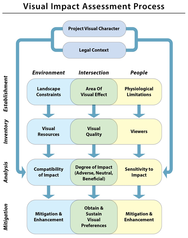
Figure 3-1. FHWA VIA Process Flow Diagram
The diagram illustrates the work flow of the FHWA VIA process. The process begins with the establishment phase, moving through the inventory and analysis phases, and concludes with a mitigation phase. Each phase is based on the interaction between people and the environment. The process is the same regardless of project complexity, but the level of effort can be tailored to fit the project.
Source: FHWA
Extended description ⇨
3.2.1 Public and Private Interests
The FHWA VIA process is based on the concept of transactional perception—the idea that visual quality is the product of a relationship between the environment and people. Experts trained in landscape aesthetics—even those that approach the field understanding that visual quality is a result of transactional perception—cannot be assured that their aesthetic training will match the visual concerns and preferences of the public. Consequently, since people are a key component of the transactional perception model, it is critical to know what the public actually values about their visual environment.
The public can be involved in the development of a VIA in several ways. The most useful and effective involvement is for the public to establish visual quality preferences for their community or corridor. Frequently, a community’s visual quality preferences have been defined or are implied in legislation, judicial rulings, or just the accumulation of a local visual tradition over time. These preferences may be stated as planning ordinances or building codes. They may be identified as protected places (such as parks and civic spaces) and by formal restrictions. The community’s visual quality preferences might also be implied in its urban character, vernacular architecture, public buildings, open spaces, width of thoroughfares, and other built evidence of a collective aesthetic.
A systematic approach to establishing visual management requirements using a public engagement process to identify visual preferences is ideal, frequently allowing VIAs to be efficiently completed by professionals. At a minimum, it is essential that the visual preferences of the public be established for a particular corridor before visual impacts can be assessed. Specific techniques for determining visual preferences and visual management goals are provided in Chapters 4 and 5 of these guidelines. These methods can be incorporated in public involvement activities conducted as part of the NEPA process.
FHWA, in compliance with NEPA and directives from the Council on Environmental Quality (CEQ), evaluates social, environmental, and economic impacts regardless of whether such impacts are inherently public or private. Visual impacts can occur to both public and private interests. Therefore, FHWA recommends that both public and private impacts on visual quality be evaluated in a VIA.
3.3 Determine Level of VIA
The importance of considering visual issues as part of the NEPA process was established in Chapters 1 and 2. Nonetheless, the assessment of visual impacts should not place an undue burden on the government entities providing those transportation services and improvements necessary for the health, safety, and welfare of the communities they serve. Authors should use a scoping tool to help determine first if a VIA is necessary, and if so, the level of detail needed to fulfill regulatory and judicial requirements.
3.3.1 Determine Whether a VIA is Needed
A decision tree showing the steps of determining whether a VIA is needed and what level of VIA is appropriate is shown in in Figure 3-2. First, you should consider whether the proposed project has triggered any impacts to the visual resources of the project area, and whether or not a VIA is required for the particular project. If a VIA is required, then determine the level of documentation needed to adequately fulfill the NEPA requirement. Neither NEPA nor the CEQ NEPA regulations prescribe any specific method for evaluating visual impacts, leaving each Federal agency to develop its own approaches tailored—as these guidelines are—to the actions of a particular agency.
If there are no noticeable visible changes to visual resources, viewers, or visual quality, a VIA would not be needed. For example, some kinds of projects such as roadway resurfacing, rehabilitation of highway shoulders, or restriping, etc., would result in no apparent change to the visual qualities of the project area. In such cases, the fact that the proposed project has no effect on its visual setting can be documented as simply “no effect.” If further explanation is warranted for why a VIA was not needed, the assessment can present further documentation, for example by utilizing one of the methods listed in Section 3.3.2 Methods for Determining the Level of the VIA below and include it.
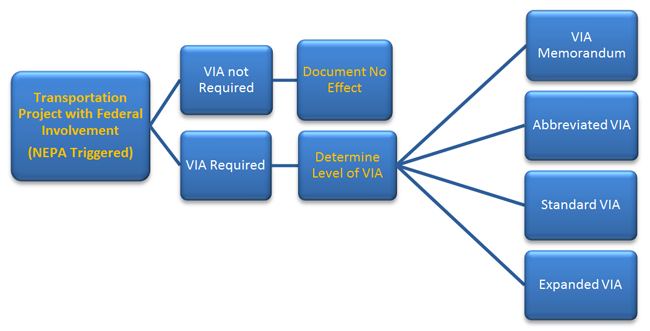
Figure 3-2. FHWA VIA Decision Tree
If a proposed highway project has Federal involvement, determine if a VIA is required. If a VIA is required, determine the level of effort needed to assess visual impacts. The FHWA VIA guidelines recognize four general levels of effort and documentation: a VIA Memorandum, an Abbreviated VIA, a Standard VIA, and an Expanded VIA.
Source: FHWA
Extended description ⇨
If a VIA is needed, the FHWA VIA guidelines provide for four different levels of documentation based on the scope, complexity, and controversy associated with a particular project. If the project and its impacts are visually inconsequential, the authors should prepare a memo to the file (VIA Memorandum). Assess routine or minor projects using an Abbreviated VIA. The level that results in a thorough examination of the visual issues associated with most projects involving new construction or substantial reconstruction is called a Standard VIA. Complex or controversial projects may require an Expanded VIA. Descriptions of the VIA document associated with each of these levels are provided in Appendix D.
The VIA is written as an independent report and the results of the VIA are then incorporated by reference and briefly summarized in the project’s NEPA document, which may be a Categorical Exclusion (CE), Environmental Assessment (EA), or an Environmental Impact Statement (EIS).
Note that the level of VIA needed is not always tied to the level of NEPA document. For instance, although a VIA Memorandum or an Abbreviated VIA may be typical for a CE or EA, there may be circumstances where a Standard VIA is needed to assess visual impacts. It is important to consult a State DOT’s environmental specialist when determining the appropriate level of VIA.
3.3.2 Methods for Determining the Level of the VIA
A VIA scoping questionnaire or a comparative matrix method can help determine the appropriate level of VIA. Either method can be used, and regardless of the method used, as the VIA is developed, evaluate whether the level of analysis and documentation is appropriate for the project and adjust as necessary to new information.
Questionnaire Method
The scoping questionnaire consists of 10 questions and provides an explanation of each with a scoring system to help determine the type of VIA. The complete questionnaire is in Appendix C, VIA Scoping Questionnaire. The questions cover two topics: environmental compatibility and viewer sensitivity. For each question, select an answer from a set of multiple-choice responses. A score is associated with each response. Total the scores to determine the type of VIA analysis and documentation.
The five questions about environmental compatibility in the VIA Scoping Questionnaire are:
- Will the project result in a noticeable change in the physical characteristics of the existing environment?
- Will the project complement or contrast with the visual character desired by the community?
- What types of project features and construction impacts are proposed? Are there particular concerns related to bridge structures, large excavations, sound barriers, vegetation removal, or other features of the proposed project that will raise concerns?
- Will the project changes likely be mitigated by normal means such as landscaping and architectural enhancements, or will avoidance or more extensive compensation measures be necessary to minimize adverse change?
- Will this project, when seen collectively with other projects, result in cumulative adverse impacts to visual resources or their visual character?
The five questions about viewer sensitivity are:
- What is the potential that the project proposal may be controversial within the community, or opposed by any organized group?
- How sensitive are potential viewer-groups likely to be regarding visible changes proposed by the project?
- To what degree does the project appear to be consistent with applicable laws, ordinances, regulations, policies, or standards regarding visual preferences?
- Are any permits going to be required by outside regulatory agencies (i.e., Federal, State, or local) that will necessitate a particular level of Visual Impact Assessment?
- Will decision-makers (including the project designers) or the public benefit from a more detailed visual analysis in order to help reach consensus on a course of action?
Totaling the scores for the 10 questions results in a sum of from 6 to 30. Based on the experience of State DOTs using a similar scoping method, the suggested level of VIA documentation necessary to address visual issues is shown in Table 3-1 below.
Table 3-1. Scores and Suggested VIA Documentation Levels
| Total score |
Recommended VIA Document |
| 6-9 |
None Needed |
| 10-14 |
VIA Memorandum |
| 15-19 |
Abbreviated VIA |
| 20-24 |
Standard VIA |
| 25-30 |
Expanded VIA |
| The sum of the scores from the VIA Scoping Questionnaire can be correlated with a suggested level of VIA documentation. |
The questionnaire is a helpful tool, but it is not definitive. If previous experience or comments from the public, local officials, or regulatory agencies indicate that visual issues may be a substantial factor in assessing the project’s social, economic, or environmental impacts, FHWA recommends preparation of a thorough VIA document regardless of the level suggested by the questionnaire method.
Comparative Matrix Method
Another method for determining the level of the VIA is to use a comparative matrix. The distinguishing attributes of a VIA, differentiated by the level of the assessment, are shown in Table 3-2, Comparative Matrix. Simply select the level of VIA with the description that best fits the anticipated scope of the proposed project.
Table 3-2 Comparative Matrix
| Project Character by VIA Level |
| Item |
Assessment Level |
| Memorandum |
Abbreviated |
Standard |
Expanded |
| Landscape Units |
One |
One |
Multiple |
Multiple |
| Controversy |
None |
None/Limited |
Local, perhaps state-wide |
State-wide or nationally organized opposition |
| Alteration of Visual Environment |
None or Minor |
Minor |
Moderate |
Substantial, even significant |
| Viewer Groups |
Neighbors and travelers |
Neighbors and travelers |
Neighbors and travelers |
Some to many specific types of neighbors and travelers |
| Key View Points |
None or Few |
One or Few |
Few to Multiple |
Multiple |
| Viewer Sensitivity |
None or Low |
Low to Moderate |
Moderate to High |
High to very high |
| Compatible with Local Plans |
Compatible |
Typically compatible |
May be compatible |
May conflict |
| Impacts on Scenic Resources |
None |
None or limited |
Potentially substantial or even significant |
Substantial or significant |
| Cumulative Impacts |
None |
None significant |
Potentially substantial or significant |
Substantial or significant |
| Permits affected by visual issues |
None |
Unlikely |
Perhaps |
Perhaps |
| Legal Challenge |
Unlikely |
Unlikely |
Unlikely or may be challenged |
May be or likely to be challenged |
| Use of Simulations |
None |
Unlikely |
Stills of key views potentially used |
Multiple stills; animations for certain complex or controversial projects |
| One method for selecting the level of effort necessary to assess visual impacts caused by a proposed highway project is simply to match the anticipated attributes of the project with the attributes typical to a particular level of assessment. |
Back to Top
In this Chapter:
- Understanding the visual character of the project
- Documenting the regulatory context
- Defining the AVE
Chapter 4. Establishment Phase
4.1 Purpose
The first phase of the FHWA VIA process is the establishment phase. The purpose of this phase is to answer three basic questions:
- What is the visual character of the proposed project? (Section 4.2, Define the Project’s Visual Character)
- Are there any legal directives or social constraints that dictate the visual quality of what can be constructed? (Section 4.3, Determine the Regulatory Context)
- To what extent is the proposed project visible? (Section 4.4, Define the Area of Visual Effect)
Answer these three questions to complete the establishment phase.
The tasks associated with the establishment phase, along with those tasks of the inventory phase, generate the baseline conditions for assessment of visual impacts.
4.2 Define the Project’s Visual Character
During the first task, authors should define the general character of the proposed project’s visual features. Focus the description on the physical attributes of the highway’s constructed elements. Authors should not reference affected environment, affected population, visual quality or visual impacts; instead, they should establish what is known about the visual character of the proposed project at the initial stage of project development.
4.2.1 Examine Existing Documents
Preparers should review the project description, purpose and need statements, scoping documents, preliminary design plans, and any other special studies for a general understanding of the visual character of the proposed project. Although information on the project’s visual character may be limited in these documents, the documents themselves will prove useful in subsequent phases of the VIA process. If existing documentation is incomplete, authors should discuss the project with other members of the project team to understand and articulate the visual character of the project’s basic design features.
Project Descriptions
Project descriptions include a descriptive narrative, maps, and figures that describe or at least infer the visual character of the proposed project. In most cases, this information is available early in the project development process even if the documentation is not official or is not final.
Purpose and Need
Purpose and Need statements for transportation projects typically include a description of the transportation issue that is the catalyst for the proposed project. It may also identify direct or indirect factors that contribute to existing visual quality or define the visual preferences of the affected population.
Scoping Documents
A project’s scoping document defines the geographic extent of the project. It also establishes the topics explored in the project’s environmental review process. Preparers should participate in the scoping process, both to inform the scope of the project and to better understand the scope of the anticipated VIA and use the findings of the scoping document and any public scoping comments for an initial understanding of anticipated impacts on visual resources or viewers. Public scoping comments may identify visual resources that neighbors consider essential to the visual identity of their community, or it may identify visual resources that travelers consider essential to their traveling experience.
Conceptual Design Studies and Preliminary Design Plans
Conceptual design studies and preliminary design plans illustrate the proposed project and help to identify potential impacts to visual resources and viewers. The level of detail available during the early stages of the design will vary and can include the area of potential effect to alternative alignments, the number of lanes, the location of intersections and interchanges, and the potential for bridges, retaining walls, and other structures. In addition to providing a rough understanding of the visual character of the proposed project, early studies and plans often include features proposed for demolition, vegetation removal limits, existing and proposed grading, and other proposed project features. Authors should use these early studies and plans to understand the extent to which existing features would be removed and where new or modified landforms, pavement, structures, or utilities would occur. Sometimes these early studies and plans even include proposed aesthetic design treatments, such as ornamental lighting or architectural enhancements, included in the project to mitigate adverse impacts.
Other Special Studies
Specialized documents related to a project may be available, which could provide additional critical information for the VIA. These include such items as design standards, such as the AASTHO Green Book, State DOT design standards and aesthetic guidance, grading plans, signing plans, lighting plans, landscaping plans, and any associated evaluations of biological, ecological, or cultural resources. Preparers should request this information, if available, or discuss these items with State DOT specialists assigned to the project team.
Construction Phasing
Construction timing (time of year, duration, phasing, and nighttime construction activities), methods of construction, equipment needed, even erosion control or re-vegetation measures, if known, may be useful background information.
Operations and Maintenance Considerations
During the preliminary design phase of a project, many design features that will affect visual resources, viewers, and visual quality are being determined. Mitigation measures and opportunities for enhancement are also likely to have been introduced. Visual impacts caused by operations and maintenance activities that will affect the project design, mitigation, or enhancement elements will need to be assessed to confirm that these design features, which may be critical to the public’s acceptance of a project, remain effective indefinitely. Operational features that may affect visual quality include functional and ornamental lighting in the corridor, vehicular headlights, changeable message signs, vegetation removal, and glare from reflective materials. Maintenance issues typically are related to use of nighttime lights to perform roadwork on the facility.
4.2.2 Document the Project’s Visual Character
Using the understanding gained from examining existing documents and supplemented by discussions with the project design team, preparers should develop a general conceptual idea of the primary visual attributes of the proposed project. This is not an exercise in detail design or mitigation-this task is only to understand the basic visual components of the proposed project that will be used to assess impacts in the analysis phase of the VIA. The visual character of the project needs to be understood and documented abstractly, without reference to the affected environment or affected population.
It is typical during the early stages of preliminary design (when completing this initial task) that the design is limited to the most general parameters. Preparers should restrict the documentation to a brief narrative of the general visual character attributes of the highway, major structures, and other associated design elements, supplemented with explanatory illustrations as necessary. Avoid including a discussion of how proposed activities may affect visual resources or the experience of viewers.
Limit documentation to the basic physical nature of the proposed project’s visual character. During preliminary design, this often means limiting discussion to describing standard design elements used by the agency.
Determine the Visual Attributes of the Proposed Highway
Scale The scale of a project has potential to impact visual quality. For highway projects, scale relates to the number of lanes and the typical cross-section of those lanes, and the width of the associated medians, shoulders, ditches, and clear zones. It also refers to the length of the project. This information is available during preliminary design for many projects. Document the visual attributes of project’s cross-section and its length.
Form The form of a proposed highway is also instrumental in determining visual impacts. During preliminary design, design is limited to the most basic forms of the highway. At this stage of the design process, the visual character of the highway is a condition of its abstract geometrics (mostly horizontal alignment, although vertical profile may also be important in some situations). Authors should document the visual attributes of the project’s geometrics and note whether the project is linear or curvilinear in plan-view.
Materials For many projects, material selection is undeveloped during preliminary design. Authors should document the visual character of any standard or known materials; describing the material’s color, texture, and other artistic attributes as appropriate.
Determine the Visual Attributes of the Project’s Major Structures
Since structures often command the attention of viewers, it is essential to document the visual attributes of the bridges, retaining walls, and noise walls proposed as part of the project. Similar to documenting the visual character of the highway, authors should document the visual character of the major structures proposed for the project as an illustrative narrative that describes the scale, form, and materials of a typical bridge, retaining wall, or noise wall.
Determine the Visual Attributes of the Project’s Common Features
Depending on the project, there may be several other common visual features in the project corridor, including signs and sign supports, crash barriers, lighting, and traffic control devices. Authors should describe the scale, form, and materials of these features in an illustrative narrative.
4.3 Determine the Regulatory Context
During the second task, authors should identify and document the local, State, regional, tribal, and Federal plans, policies, and regulations related to visual resources, views, or visual quality that apply to the area affected by the proposed project, particularly noting any references to visual preferences.
4.3.1 Review Documents
Refer back to Chapter 2, Regulatory Context, for a reference list of regulations and other documents to consider. Understanding the regulatory context includes identifying and interpreting the plans, policies, and regulations established by the jurisdictions adjacent to the project corridor. In some instances, the project corridor may not encroach on a protected or sensitive visual resource but does affect views from or to a sensitive resource. These cases warrant evaluating the plans, policies, and regulations pertaining to the sensitive resource. An example is a locally designated scenic trail with a roadway corridor close by and views affected by changes from the proposed project.
In addition to those that are directly related to visual issues, there may be plans, policies, or regulations related to other protected biological, ecological, or cultural resources that could substantially affect the discussion of visual impacts (for example, a project affecting the habitat of wildlife species that are the subjects of wildlife observation). By engaging other resource specialists who are conducting their own impact assessments, it is possible to anticipate impacts on other resources that may contribute substantially to the visual character of a project area.
In addition to directing the design of a project, regulatory documents are evidence of a community’s visual preferences. These preferences may be stated in the documents or they may need to be inferred. Preparers should use interviews of local administrators and civic leaders to fully understand the implications of these documents and how they may be used in completing the VIA.
4.3.2 Document the Regulatory Context
Authors should document the project’s regulatory context in the VIA by listing and discussing such plans, policies, and regulations as evidence of the public’s visual preferences. A community’s comprehensive plan, for instance, may address protected landscapes, such as parks, nature reserves, or historic sites that are not only visually important to the community but may indicate what specific resources are visually valuable. Other policy and regulatory documents, including municipal ordinances, may offer clues to what is visually important to a community, such as understanding a preferred architectural style based on building code restrictions. These documents do not necessarily dictate what will or will not be permissible in the project corridor, but they provide an insight into a community’s visual preferences. The implications of the public’s visual preferences will be explored further during the discussion of existing visual quality in the inventory phase of the VIA.
The review of a community’s planning, policy, and regulatory documents may not reveal anything pertinent to visual quality, visual resources, or viewers. In such a case, authors should acknowledge that there are no plans, policies, or regulations that affect or are affected by any visual issues associated with the proposed highway project.
4.4 Define the Area of Visual Effect
The area of project visibility is referred to as the Area of Visual Effect (AVE). It is determined by the physical constraints of the environment and the physiological limits of human sight. To define the AVE, it is necessary to understand the three types of viewsheds—static, dynamic, and restricted. To describe the AVE, it is necessary to understand landscape units. These concepts are described in this section.
4.4.1 Consider Limits to the View
Physical Constraints of the Environment
The environment is physically constrained by landform, land cover, and atmospheric conditions.
Landform is the most basic constraint. It is the element most likely not to be modified or modified only in a localized and limited manner during construction. It is, therefore, the most prevalent physical constraint in establishing an AVE. Landform provides perspective for a viewer and it obscures views. Understanding the nature of the landforms in which a project will be constructed is the fundamental basis for defining visual quality and visual impacts. Landform is best understood using a topographic map imposed on a satellite image of the project corridor. Landform can be documented as a two-dimensional contour map or a three-dimensional digital terrain model (DTM).
Landform alone, however, provides an inaccurate depiction of the physical constraints inherent in the project corridor. By itself, landform provides a lunar view of the world-a world devoid of vegetation and structures-a world without land cover. Land cover is critical for determining the physical constraints of the environment. Vegetation and structures can become obstacles, obscuring views. Conversely, occupied structures can frequently expand views. With the ever-increasing sophistication of computer modeling, adding vegetation and structures to the corridor’s topographic information to establish actual physical constraints will become increasingly possible and is preferred for the VIA.
Physical constraints can be further restricted by atmospheric conditions—smoke, dust, fog, or precipitation that can reduce visibility, at least temporarily. It may be important to recognize and compensate for these limitations in an inventory of the AVE.
Physiological Limits of Human Sight
In addition to the physical constraints of the environment, the extent to which the project is visible is constrained by the physiological limits of human sight. Location, proximity, and light are instrumental in defining the physiological limits of what viewers can see.
- Location is defined as the topographic position selected as a key view. A key view is usually selected because it is either critical or representative of the visual character of either the environment or the project.
- Proximity of the viewer to an object is defined using three distinct distance zones: foreground, middle ground, or background.
- Light is essential to seeing, but light is not uniform and the quantity and quality of light can substantially alter perception. The largest shift is between day and night. During the day, people see color; at night, without artificial light, they don’t. The delineation of objects also becomes blurred—during the day, fine details on separate objects are visible; and at night, those objects become a single dark mass devoid of nuance. A similar shift occurs over distance. Color and individual forms fade as distance increases and elements merge into a single impression.
4.4.2 Determine Viewsheds
There are two types of viewsheds—static and dynamic. Both types of viewsheds are defined by what people can see in the environment and are the result of the intersection between the physical constraints of the environment and the physiological limits of human perception. Static viewsheds are what neighbors of the road see from a stationary location. Dynamic viewsheds are what travelers on the road see as they move through the landscape. The AVE is the sum of the viewsheds of all travelers with views from the road and all neighbors with views of the road. Identifying the static viewsheds of neighbors and the dynamic viewsheds of travelers is critical to accurately defining the AVE.
Static Viewsheds
A static viewshed is defined as what can potentially be seen in 360° from a single view point. While traditionally only landform is considered in defining static viewsheds, it is more accurate to consider both landform and land cover.
The area that comprises a static viewshed need not be contiguous. In plan, a static viewshed is frequently spotty with foreground and background views visible and the middle-ground obscured by landform, vegetation, or structures, as shown in Figure 4-1, Mapping Static Viewsheds.
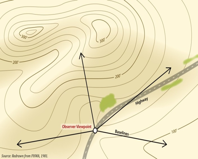
Figure 4-1. Mapping Static Viewsheds
A traditional static viewshed is defined by what can be seen in 360° from a single location. The illustration shows a static viewshed from a single point along a highway, such as from a scenic overlook.
Source: Redrawn from FHWA, 1981
Dynamic Viewsheds
Establishing a viewshed for a traveler moving along a corridor is more complicated than defining a static viewshed. To understand this concept, consider the experience of the driver traveling through a hilly countryside. As the driver rides up and over hills and into the next valley, the landscape is being presented as a continuously unfolding series of viewsheds. As the car climbs up a hill, the viewshed gets more blocked by the hill in front of it, until the car approaches the hill’s crest and a new expansive viewshed of the valley below is progressively revealed, first with views in the distance, then in the mid-ground and finally in the foreground when the car finally rolls over the top of the hill. These dynamic viewsheds are typical of a traveler’s viewshed.
Viewsheds are directional to a traveler on a highway. The viewshed for a traveler moving in one direction can be quite different from that of a traveler moving in the opposite direction, even at the same point along a highway. Also, the viewshed for a driver is more constrained by direction than it is for a passenger, who has more discretion to look to the side or even behind.
For a traveler, the crest of the roadway’s vertical profile separates viewsheds but the transition between one viewshed and another is not that distinct-one rolls into the other. The boundary is fuzzy. Mapping the dynamic viewshed of a traveler has traditionally been difficult and has usually been approximated by creating a composite viewshed composed of a series of static viewsheds from selected locations along the highway, as shown in Figure 4-2, Mapping Dynamic Viewsheds.
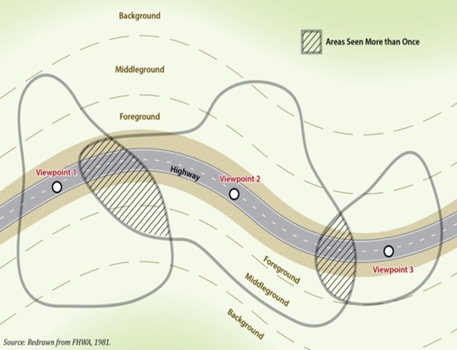
Figure 4-2. Mapping Dynamic Viewsheds
The viewshed of a traveler moving along a highway is dynamic; it is constantly changing. It is difficult to map a dynamic viewshed. A map of a dynamic viewshed is usually represented by merging a series of static viewsheds from selected locations into a single composite viewshed.
Restricted Viewsheds
Static viewsheds that are based only on landform and not constrained by any other obstacles generate the largest possible AVE. That is why they have traditionally been used to analyze visual impacts—they allow for the “worst-case” scenario. Most landscapes, however, contain some vegetation or structures that obscure views and restrict the potential viewshed. Given that obstacles frequently obscure views, and the inherent constraints of human perception, viewers are typically restricted to seeing only a few miles, even on a clear day, rendering the AVE much smaller than predicted by traditional viewshed analysis. Views are restricted by either land cover or atmospheric conditions.
Land cover Viewsheds are reduced by physical objects that interfere with a viewer’s line-of-sight, as shown in Figure 4-3, Land cover. These objects, however, can easily be altered. Therefore, in determining viewsheds, it is important to recognize the existing landscape and the potential landscape. Trees may block views of the proposed highway for adjacent residential neighbors now, but how likely are they to remain for the life of the roadway? The ability of trees to block undesirable views may be so important that the VIA specifies that they should be retained as part of project mitigation.
Atmospheric Conditions Besides the solid obstacles that obscure views, a viewshed can be limited by atmospheric conditions-smoke, dust, fog, or precipitation can reduce the apparent size and alter the shape of a viewshed, at least temporarily, as illustrated by the photograph in Figure 4-4, Atmospheric Conditions. Sometimes these atmospheric obstacles are episodic, like dust, fog, or precipitation that occur predictably either daily, weekly, or seasonally, altering the viewshed accordingly. It is important to recognize these limitations while conducting an inventory to avoid errors in establishing viewsheds.
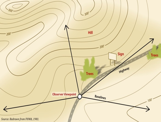
Figure 4-3. Landcover Restrictions
Physical objects, such as trees and buildings, may restrict views and limit the area contained in a viewshed.
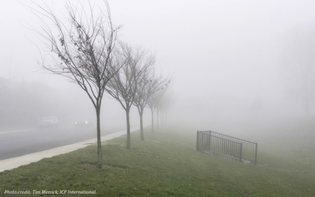
Figure 4-4. Atmospheric Conditions
Smoke, dust, fog or other precipitation can reduce the size of the viewshed. Where atmospheric conditions are episodic, repeating daily, seasonally, or annually, include them in determining the area of a viewshed.
Tools for Determining Viewsheds
Tools used to help establish viewshed limits include topographic mapping, satellite imagery, land use and vegetation mapping, and DTMs. Of these, DTMs offer the most efficient and effective way of determining viewsheds. As Geographic Information Systems (GIS) become increasingly sophisticated and include information on the location and massing of vegetation and structures as well as satellite imagery, topography, climate, and land-use, viewsheds derived from GIS data will progressively become more accurate at defining actual viewsheds.
Traditionally, a project’s viewshed is initially delineated by using a DTM to map it, as illustrated in Figure 4-5, Digital Terrain Model Map, using only topography. Adjust this preliminary map by conducting a field review that locates obscuring elements such as vegetation and structures that may further limit the visibility from and to the highway.
The ability of DTMs to create accurate viewsheds is limited by the digital information available to construct the model. If the model accounts for terrain but not vegetation, the built environment, or the presence of typical atmospheric conditions, it will not generate an accurate viewshed without further field-verification. Advances in DTM modeling may overcome these limitations in the future.
Vegetative cover and atmospheric conditions can vastly affect the visibility of a project. Viewsheds based solely on topography should be considered preliminary, subject to adjustment made during a field review of the project corridor. Although viewsheds can be initially developed using information gleaned from electronic databases, field observations are important for verifying viewsheds and determining the actual landscape units from which visual impacts will be assessed.
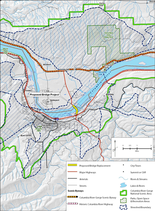
Figure 4-5. Digital Terrain Model Map
A DTM can be produced using GIS. A DTM can be used to delineate a project’s visibility and later to complete additional analysis. The hashed line represents the viewshed from and to the bridge which is the location of the key view.
Field Observations
Use field observations to more fully understand the project and its context. You should review any documents related to the visual character of the proposed project or visual character of the project corridor before conducting the initial field visit. Field observations may determine if it is necessary to search for additional published and unpublished information to assess visual impacts or if existing documentation is adequate for conducting a VIA. It will also allow for the refinement of viewsheds into landscape units.
Preparation
The primary information needed to evaluate the project corridor is a topographic map indicating the routes of the proposed alternatives and their respective project limits, and a general understanding of the proposed project’s features and removals. It is also helpful to know prior to the field visit if there are any officially designated scenic routes, wild and scenic rivers, historical resources, or other sensitive visual resources that could affect the assessment of visual impacts. (How to prepare and conduct a field visit is outlined in Appendix E: Field Reconnaissance Techniques.)
Virtual Field Visit
Preparers should conduct a “virtual field visit” prior to an actual field survey to become familiar with the visual character of the project area. A virtual field visit can also be used to help identify viewers that may be affected by the proposed project, particularly if it is possible to determine land uses.
Many State DOTs regularly produce aerial photography and record bi-directional street views of their corridors that provide an excellent basis for a virtual field visit. Similarly, many Federal and State agencies and local units of government have extensive libraries of aerial photography, including historic views, that may reveal useful information for a VIA. If unavailable through a government source, a virtual field visit can be conducted using commercial internet satellite mapping and imaging sites. Similarly, electronic or printed versions of topographic maps provide a detailed understanding of landforms, water bodies, land use, roadways, trails, and recreational areas essential for conducting a VIA.
The utility of these maps, aerial photographs, and satellite images can be greatly enhanced by overlaying the various alternatives of the proposed project to identify areas that need to be more carefully examined in the field.
When conducting a virtual field visit, be aware that recorded information, especially photographic information, is subject to unintentional distortions. Most cameras fail to depict the more panoramic view that people have of the landscape along the roadway. Consequently, a virtual trip frequently fails to capture the context of a highway that includes significant views to the surrounding landscape, such as views of a treeline or mountains in the distance. Also, be aware that limited image quality or atmospheric conditions can contribute to inaccurate portrayals. Nonetheless, for minor projects that require only a VIA Memorandum or an Abbreviated VIA, a virtual field visit may be sufficient.
Live Field Visit
During the field visit, you should become familiar with the project area, identify if there is a need for additional background information, and identify a preliminary AVE. While additional field visits to develop thorough inventories of visual resources and viewers may be necessary, it is advantageous to begin these inventories with this first visit, including recording pertinent information on maps and photographing visual resources and viewers.
4.4.3 Establish and Describe Landscape Units
Establish Landscape Units
The geographic unit on which impacts on visual character, viewers, and visual quality are assessed is called a landscape unit. Landscape units are defined by viewsheds and landscape type. A landscape unit can be conceived of as a spatially defined landscape with a particular visual identity—a distinctive “outdoor room.” It can be large or small, depending on how the landscape is divided into analytically manageable pieces of real estate. For projects using a VIA Memorandum or an Abbreviated VIA to assess visual impacts, the AVE typically forms a single landscape unit. For projects using either a Standard or Expanded VIA, the AVE is typically divided into multiple landscape units. It is possible, however, that a single landscape unit may suffice for even those projects.
A landscape unit is visually homogeneous with only one viewshed and one landscape type. However, there are instances where a landscape unit can be heterogeneous with more than one viewshed or more than one landscape type. For example, if the project is complex enough to require either a Standard or Expanded VIA to adequately assess impacts, FHWA recommends that the landscape unit be differentiated by viewshed even if the whole corridor has only one landscape type.
Landscape units are often established using aerial imagery and they often correspond to land use types, not only identifying visual character of the affected environment but also that of the neighbors who will be affected.
Authors should determine the most effective way to frame and establish landscape units and attempt to set them up in a manner that reduces the need for repetitive discussion and analysis. Since the discussion of visual impacts will be based on analyzing changes to the visual character of landscape units, focus on substantial changes to visual resources, viewers, or visual quality of landscape units that are so visually unique that a separate analysis is necessary. Where the visual character and the visual impacts on several viewsheds are similar, group them into a single landscape unit. Although uniformity in the visual character of a landscape unit is preferred, there can be minor variations created by visually unique areas within a landscape unit. If, however, as the VIA progresses, these anomalies begin to complicate either the description of baseline conditions or the analysis of visual impacts, that particular area may warrant becoming its own landscape unit.
Describe the Landscape Type
To describe the landscape type of a landscape unit, begin with an understanding of the unit’s general context—including where it is located geographically, ecologically, and socially—and add local details that make the landscape unit visually distinctive.
Geographically, identify the region of the country where the landscape unit is located. Is it in the high plains of the west or in the piedmont of the east? What are the region’s general land forms? Are there mountains, plateaus, glacial drumlins? Are there exposed rock formations? Are the rocks igneous or sedimentary? Are there scattered erratics? What kind of soils does it have? Is it loamy farmland or shifting sand dunes? What is its climate? Is it typically hot, dry, and clear, or moderate, rainy, and foggy? What aspects of the visual character of the larger region are found locally? Are there any that are particularly accentuated or missing? What makes this landscape unit visually unique? How does the nature of the landscape unit’s geography affect visibility and define other attributes of visual character? These questions are meant only to be a catalyst for documenting a description of the distinctive visual character of the landscape unit’s geography.
Ecologically, identify the biological community of the landscape unit. What plants and animals occupy the viewshed? How tall and dense is the vegetation? What species dominate? What are their forms? Is their foliage seasonal? Does it change color from spring to fall? Are their flowers visible? How does the vegetation affect visibility? How prolific are the animals? What are their sizes? Do they congregate? What features of the visual character of the region’s biological community are found locally? Are there any regional features that are particularly accentuated or missing locally? What makes this landscape unit visually unique? How does the nature of the landscape unit’s ecology affect visibility and define other attributes of visual character? Again, these questions are not meant to be definitive, only a catalyst for documenting a description of the distinctive visual character of the ecological systems within the viewshed.
Socially, identify the land uses in the viewshed. What sort of pattern have they created across the landscape? Is it imposed, is it responsive to the native landscape’s natural systems, or has it transformed either the geography or ecology of the natural systems? To what degree is it artificial and obviously constructed by people? Is the land use uniform or diverse? What features of the visual character of the land uses are typical in the region? Are there any regional land uses that are particularly accentuated or missing locally? What makes this landscape unit visually unique? How does the nature of the land uses affect visibility and define other attributes of visual character? Again, these questions are not meant to be definitive, only a catalyst for documenting a description of the distinctive visual character of the land uses.
4.4.4 Document the AVE
Authors should document the AVE by creating a map of the AVE boundary that was established through the identification of viewsheds and providing a narrative description of the landscape units.
Maps
A map showing the context of the project area within the State is appropriate for projects being documented with a Standard or Expanded VIA. This context map, illustrating the State’s bio-geographical communities and its transportation network, shows how the project area fits into the larger environment. Show and label political boundaries and political units on the context map to the degree that their policies, plans, or ordinances affect or define visual preferences. Add labels to dominating visual features such as water bodies and roads to orient the reader and reviewer of the VIA.
Another map delineating the AVE is necessary to document the findings of the establishment phase. A clear satellite image of the project area is a good base on which to overlay the AVE and its landscape units. This map is appropriate for an Abbreviated, Standard, or Expanded VIA. Delineate, name, and label the landscape units. Use a descriptive name. These names can be a combination of landform and land cover—for example, “Bottomland Forest;” a locally known name—such as “Lewiston Woods;” or some other uniquely descriptive label.
Narrative Description
Authors should write a narrative describing the general landscape type of the landscape units to accompany and explain the map. This description is neither a detailed list of individual visual resources nor a specific account of visual character, but rather focuses on the major visual attributes of the landscape that differentiate one landscape unit from others-an alpine forest on one side of a ridge and a grassland on the other. The focus is on overarching characteristics, not specific visual resources.
Images
Photographs or drawings depicting the general landscape character of the AVE may be included, but may not be necessary if such images will be used in the inventory of the affected environment, which is the next phase of producing a VIA.
Back to Top
In this Chapter:
Establish baseline conditions by evaluating:
- Visual character
- Viewer preferences
- Visual quality
Chapter 5. Inventory Phase
5.1 Purpose
The purpose of the inventory phase is to define the existing status of the affected environment and the affected population and the existing or preferred condition of visual quality. To accomplish this purpose, answer three basic questions during the inventory phase:
- What is the existing visual character of the AVE? (Section 5.2, Affected Environment)
- Whose views in the AVE would be affected by the proposed project? (Section 5.3, Affected Population)
- What do people like and dislike about the existing visual character of the AVE? (Section 5.4, Affected Visual Quality)
Authors should answer these three questions to complete the inventory phase of the VIA. The inventory phase along with those tasks of the preceding establishment phase, generate the baseline conditions from which visual impacts will be assessed.
5.2 Affected Environment
The existing visual character of the AVE is determined by its visual resources. During the inventory phase, continue and refine the examination of landscape units begun in the establishment phase by identifying the visual character of the visual resources that compose each landscape type.
5.2.1 Inventory the Natural, Cultural, and Project Environments
Visual resources and the environments they dominate can be divided into three categories: natural, cultural, and project. Although these divisions are artificial (Where is the line between natural and cultural environments?), dividing the affected environment into natural, cultural, and project environments to determine their visual character ensures a thorough inventory of the visual character of the AVE.
Tips for Conducting the Inventory
The extremes of the natural—cultural spectrum are easily recognized—no one mistakes Yosemite National Park for downtown San Francisco or the Everglades for Miami Beach. Yosemite and the Everglades are recognized and described by most people as being natural landscapes, despite obvious intrusions constructed by people. Downtown San Francisco and Miami Beach are recognized and described as primarily cultural landscapes, although their natural settings contribute significantly to their visual character. In contrast, it is difficult to categorize the rural landscapes that dominate vast ranges of our country as being strictly natural or cultural landscapes. However, it doesn’t matter in which category a particular landscape is cataloged—what matters is the consistency with which a specific type of landscape is cataloged and that all significant visual resources associated with the natural, cultural, and project environments are inventoried.
A landscape devoid of built elements (vertical and horizontal construction), is a natural environment. By this definition, farmland, even though it is manipulated, is also a natural environment. If the landscape is composed of built elements, or is otherwise highly manipulated, it is a cultural environment. A suburban landscape defined by its buildings and pavement is a cultural landscape even though it has yards and trees. The project environment is less subject to categorical problems—it is the landscape inside of the right-of-way, regardless of whether it is a natural or cultural environment.
Authors should catalogue very specific items in the inventory of the natural, cultural, and project environments. For the natural environment, the list includes: air, land, water, vegetation, and animal life. For the cultural environment, the list includes: buildings, structures, transportation infrastructure, other built artifacts, and art. For the project environment, the list includes: alignment, profile, cross-section, grading, drainage, pavement, signs, signals, plantings, and other elements of a modern highway. These lists are basic but usually provide a sufficient description of the visual character of the AVE. Other items may be included in these lists, depending on the project’s landscape setting. However, authors should consistently categorize any additions, not only within one VIA document but for all VIA documents assembled by the same State DOT.
Preparers should inventory only the visual character of the AVE (i.e., the visible physical attributes). At this initial step in the inventory phase, refrain from evaluating existing visual quality—that is, from assigning a value to the affected environment. Since visual quality is a value placed on visual resources by viewers, visual quality can only be assessed once both the visual character of the existing landscape and viewer preferences are known.
Although many visual resources can be quantitatively measured, these measurements are typically not as important as qualitative descriptions. For example, a lake of 200 acres may be quite large and visually unique in some States and average-sized and visually common in others. Knowing the qualitative measurement (it is a large and unique or average-sized and common) is more helpful in determining the contribution it makes to local visual quality than knowing the area of its surface (200 acres).
Visual Character of the Natural Environment
Specific natural resources may vary across the country. Classifying these resources leads to general groupings of resources associated with land, water, vegetation, animal life, or atmospheric conditions. Together these resources form a composition. Report the visual character of the composition of natural resources in the VIA. See below for individual components as a reminder to include them in the inventory.
Land The attributes of visual character associated with land include the landscape’s physiography, particularly its morphology (landform) and the composition of its exposed surface (land cover that is not water or vegetation). Describe the landscape’s form, its spatial qualities, and the nature of its materials.
Water To describe the attributes of visual character associated with water, you should identify whether each water body appears to be flowing or an impoundment (e.g., natural or constructed lake or pond). If water is flowing through the landscape, describe the width, gradient, velocity, turbulence, and turbidity of the stream. Describe its alignment and cross-section including the form, spatial qualities, and materials of its embankments. Add any other distinguishing visual attributes. If the water is an impoundment, describe its visual attributes such as the size of the water body, the shape and spatial qualities of its perimeter, turbidity, the nature of its littoral or intertidal zones, and any other distinguishing visual attributes.
Vegetation The description of the visual character of vegetation is most critical for defining the visual character of any landscape, and how it affects spatial quality. You should describe the presence or absence of vegetation; whether it is native, naturalized, or cultivated; its height and density; its artistic description, including its form, shading, color, and texture; and any other distinguishing visual attributes. In particular, it is important to note seasonal changes, such as the presence of flowers, fruit, and seasonal color.
Animals Animals, wild or domesticated, can be an essential part of a landscape. Domesticated farm animals are a readily identified attribute of rural agricultural landscapes. Wildlife can be critical to the visual character of a landscape. In particular, mammals and birds, even if only occasionally visible, contribute to the visual character of a landscape. Often, the presence of certain animal species is a visual indicator of a landscape’s vitality and is intertwined with a landscape’s unique identity. Note the wildlife species likely to be observed, particularly those species that may attract viewers or hunters, such as whale or bird migrations, herds of large mammals, or seasonal flocks of waterfowl that will contribute to the visual character of the corridor.
Atmospheric Conditions Atmospheric conditions, although passing, contribute to the visual character of a particular landscape. The typical presence or absence of humidity, fog, and dust can reduce or alter visibility. Predictable amounts of precipitation, either as rain or snow, can change the visibility of the landscape. Rain with its darkened sky and snow covering the ground may change a landscape’s luminosity (i.e., level of brightness) and, key views and distance zones (as discussed later in this section). Noting the frequency, even periodicity, of such obscuring or altering phenomena adds a caveat to description of a landscape’s visual character. For instance, the visual quality of the enclosing fogginess of the darker Olympic Peninsula is quite different than the open starkness of the very bright Four Corners of the desert southwest.
Visual Character of the Cultural Environment
For the inventory of the cultural environment, you should identify the visual attributes of cultural resources contained in the project’s AVE, including the visual character of its buildings, infrastructure, structures, and other artifacts and art. Like the attributes associated with natural visual resources, cultural resources interact with each other to form a composition. Authors should report the visual character of the composition in the VIA. The individual components are listed below as a reminder to include them in the inventory.
Buildings Buildings are enclosed structures that are or have been used or occupied by people. Buildings are often the dominant human-constructed objects in a landscape. Focus on describing the attributes that compose a building’s visual character and avoid evaluating the building’s value to society or potential viewers (this will come later in the VIA process). To describe visual character, focus on the building form, scale, massing, materials, and architectural style and detailing. Discuss the building’s orientation; the patterns of light and shadows it creates; its artistic attributes like color, pattern, and texture; and its site-specific setting, particularly if it obstructs views. The building’s historic status may also be critical. Its current and past occupants, the architect that designed the building, the client for whom it was built, or the contractor who constructed it may all become significant pieces of information that later affect the perception of visual quality. Finally, identify the views that the building would afford of the proposed project. A good source for understanding buildings and how to inventory them is described on a web site (https://www.nps.gov/orgs/1739/index.htm) sponsored by the National Park Service.
Infrastructure In addition to buildings, the country’s infrastructure systems add to visual character of the cultural environment. Railroads, airports, harbors, roads, canals, dams, electrical and telecommunication utilities, pipelines, sewer and water systems, solar arrays, wind turbines, and other infrastructure provide a special set of buildings, structures, and associated artifacts that, as part of an intermodal system of moving people, goods, and services, can affect the visual character of an adjacent highway project. A major visual attribute of infrastructure is its linearity. Infrastructure systems can stretch for miles, across whole States, between termini. Since these extended lines can substantially alter the character of the natural and cultural landscapes, be sure to identify them in this inventory phase of the VIA process.
Structures Structures are engineered elements that provide a necessary social function but are not buildings or part of a larger infrastructure system. For a VIA, these may be walls, towers, and other constructed items erected to serve a single utilitarian function. Although some structures have architectural treatments, most do not, allowing form and materials to be dictated by functional requirements. Like the inventory of buildings, concentrate on describing the structure’s visual character—its form, scale, massing, materials, construction method, and engineering detailing. Also, discuss orientation and the patterns of light and shadow created by structures, and the site-specific setting for each structure, particularly if it obstructs views. An understanding of the historical context and purpose of a structure, including an overview of the personalities and organizations involved in its construction, is essential for later determining its contribution to the visual quality of the project area.
Artifacts and Art Some cultural visual resources, although not buildings, infrastructure, or structures, still can contribute to the visual character of the project area. Many of these items, classified by the VIA process as artifacts, are those items that do not fit neatly into any other category. In particular, public art can be a defining element of a landscape’s visual character. Catalogue artifacts and art in a manner similar to that recommended for buildings. Again, refrain from assigning a value to these artifacts but focus instead on describing their visual attributes and visual character.
Visual Character of the Project Environment
The list of visual resources in the project environment includes highway geometrics, grading, constructed elements, vegetative cover, and other ancillary visual elements found in the corridor of a modern highway. As with natural and cultural visual resources, describe only the visual character of the project’s physical elements to the extent they currently exist. During this step in the inventory phase of the VIA, before the values of prospective viewers are known, avoid assigning values (visual quality) to these project elements.
The project resources interact to form a composition. Authors should report the visual character of the composition in the VIA. The individual components are listed below as a reminder to include them in the inventory.
Highway Geometrics To inventory highway geometrics, authors should document the visual character of the highway’s alignment, profile, and cross-section, noting the degree to which they are visually coordinated.14 The geometrics of a highway have a tremendous influence on visual impacts, not only to the adjacent natural and cultural environments but also within its own domain. Highway geometrics dictate, to a large degree, what can be seen and what cannot be seen by travelers. The curviness or straightness of the horizontal alignment, the slope and amplitude of its vertical profile, and the width of its surface all affect the visual character of the roadway corridor. Documenting the existing state of these elements and how these elements will be modified by the proposed project is a critical step in the development of a VIA.
Grading The existing grading or the grading that will be necessary to accommodate the proposed project is tied to a highway’s geometrics. The visual character of the physical forms generated by grading of the right-of-way, such as grading of slopes, the need for cuts and fills, and the presence of rock cuts and retaining walls, all affect the visual quality. The surface appearance of rock cuts and retaining walls also affect the visual character of the project area.
Constructed Elements A typical highway has two major types of elements that are constructed onsite and that may affect the visual character of the project area: pavement and structures. Pavement includes any surface on which vehicles or people can travel; the road, shoulder, parking lots, sidewalks, and trails are examples of pavement that could affect visual character. Structures are major constructed elements—bridges, viaducts, and culverts; retaining walls; noise walls; and other large scale visual elements—that are necessary components of the highway.
To document the visual character of these constructed elements, describe their form, scale, massing, and material. Like the descriptions for the visual character of cultural visual resources, the descriptions used to define the visual character of a highway’s constructed elements can include a definition of the setting and orientation of the structures. It may also describe the interplay between light and shadow and its artistic attributes like color, pattern, and texture. It should define its site-specific setting, specifically if it obstructs or generates views—this is particularly true for bridges. The historic status and designer of a structure may also be critical in establishing its contribution to the visual character of the project area.
Vegetative Cover The area outside the footprint of the highway’s constructed elements, a corridor often incorporates vegetation to reduce erosion. The vegetation may be native, introduced, or feral. Authors should describe the visual character of the corridor’s vegetative cover by identifying its density, distribution, and species composition. Include artistic attributes of the plants (such as seasonal color) and the ecological setting.
Vegetated rights-of-way are not uniformly present in all regions of the country. In some parts of the United States, vegetation on rights-of-way is minimal or even absent. Regardless of the extent of vegetation, it is still necessary to describe this aspect of the visual character of the right-of-way.
Ancillary Visual Elements Other essential components of a highway contribute to the visual character of the project corridor. The most prominent of these elements are traffic control devices, including signs and semaphores, which direct traffic. Identify the visual character of existing and proposed traffic control elements to understand the existing and proposed visual character of the project corridor.
5.2.2 Document the Visual Character of the AVE
Authors should document the visual character of the AVE with maps, a narrative description, and selected images. Document the inventory of the visually distinctive resources and visual character of the natural, cultural, and project environments for each landscape unit. Remember that for the natural environment this is the visual character of land, water, vegetation, animals, and atmospheric conditions. For the cultural environment, it is the buildings, infrastructure, structure, and artifacts and works of art. For the project environment, it is highway geometrics, grading, constructed elements, vegetative cover, and other ancillary visual elements.
The visual character of the AVE interacting with the visual preferences of the affected population will determine the existing status of the AVE’s visual quality.
Maps
Using the map of the AVE and its associated landscape units produced for the establishment phase as a base, you should graphically highlight and label those visual resources that represent the visual character of the natural, cultural, and project environments for each landscape unit. Graphically highlight and label other distinguishing visual features that make the landscape unit unique. The details and complexity of maps will usually reflect the level of the document being produced—Abbreviated VIA, Standard VIA, or an Expanded VIA. It is unnecessary in most cases to produce a map for a project whose visual impacts are assessed with a VIA Memorandum.
Narrative Description
Authors should list the attributes and describe the visual character of the specific visual resources of the natural, cultural, and project environments that compose the landscape of the AVE. The narrative description of the visual character of each landscape unit will form the basis for analyzing the impacts caused by a proposed project. As with maps, the level of detail in the narrative should correspond to the complexity of the project and level of VIA being produced.
Images
Photographs or drawings of specific attributes of visual resources that contribute to the landscape character of the AVE and each of its landscape units are a critical component of the descriptive narrative. As the complexity of a project and the sophistication of the VIA increase, the need to use photographs and other illustrative material to document existing visual character increases.
5.3 Affected Population
The second task of the inventory phase is to answer the question, “Whose views in the AVE does the proposed project affect?” The population affected by the proposed project is referred to as viewers. In the inventory phase, viewers are defined by their relationship to the proposed highway project and their visual preferences.
There are two distinct groups of viewers: neighbors and travelers. Neighbors are those people who are adjacent to the highway and have “views of the road.” Travelers are those people who are using the highway and have “views from the road.” Neighbors and travelers can be further subdivided into categories that help to establish viewer preferences and their sensitivity to changes in visual resources. Those categories are explained in this section. Viewer preferences are determined as part of the inventory phase of the VIA. Viewer sensitivity is determined later, in the analysis phase.
Like the divisions of the affected environment, the division of viewers into groups of neighbors and travelers is artificial when applied to individuals. The categories of neighbor and traveler do not represent real individuals as much as they represent real situations in which individuals find themselves. Individuals actually “wear many hats” and are not easily categorized—a residential neighbor can also be a commuting traveler, for example. It is similar to any other label attached to a person—a farmer is not always farming; a shopper is not always shopping—a farmer and a shopper could be the same person but their interests, when farming or shopping, can be very different. Similarly, the residential neighbor who becomes a commuting traveler may have different or even conflicting interests when sitting at home from when sitting behind the wheel of a car. Rather than trying to make one set of interests subordinate to the other, account for both sets of interests.
For an Abbreviated VIA and frequently for a Standard VIA, the simple division between neighbors and travelers is sufficient for assessing visual impacts. For complex or controversial projects that require the use of a Standard or Expanded VIA, it may be necessary to subdivide neighbors and travelers into smaller sets of viewer groups, as discussed below.
5.3.1 Neighbors (Views of the Road)
Definition
The term neighbor does not always mean that a person is adjacent to the roadway. Rather, it refers to people who are not traveling on the roadway but may see it from their geographic location in the AVE.
Land-use is a useful way to subdivide neighbors into viewer-groups. Land-use identifies who occupies property near the highway, suggesting how they use the highway and providing clues to their visual preferences.
It is possible to identify and differentiate each viewer group by a set of unique interests in visual quality based on land-use. If a project is so complex and controversial that it is necessary to divide neighbors into several viewer groups, using local land-use designations may expedite further analysis. Dividing neighbors into residential, recreational, institutional, civil, commercial, retail, agricultural and industrial viewers helps classify groups. You should create groups that would be recognizable by the affected population.
Viewers who are traveling (but not on the highway under study) are also considered as neighbors, even though they may be pedestrians, bicyclists, or motorists on other routes. Consider these viewers as an extension of some other group of neighbors. Reserve the term traveler for those viewers traveling on the highway that is the subject of the VIA (Section 5.3.2, Travelers (Views from the Road)).
The following descriptions identify the members in each viewer group and the standard visual preferences of that particular viewer group. Visual preferences are defined by a viewer group’s desire for natural harmony, cultural order, and project coherence (see Section 5.4 for a discussion of these terms).
Types
Residential Neighbors Residential neighbors live within viewing distance of the proposed highway. This includes residents of single-family homes, condominium or apartment dwellers, and others who occupy permanent shelter. They can be owners or renters and tend to be permanent rather than transitory. Their visual preferences tend toward a desire to maintain the existing landscape as it is—they settled where they are for a reason, including how their neighborhood looks. They are not very interested in change, even change that purports to improve the quality of their lives, unless they participated in defining the changes. Depending on their location, residential neighbors are often interested in cultural order and natural harmony, with less emphasis on project coherence unless it impacts their ability to appreciate the other two aspects of visual quality.
Recreational Neighbors Recreational neighbors provide or participate in recreation within the AVE. Recreation includes organized sporting events, indoor and outdoor leisure activities, and cultural events. Those who supply a recreational service for others to consume and enjoy, are sometimes permanent; visitors are consumers of the recreational service and are more transitory. The visual preferences of recreational neighbors tend to be focused on and associated with their recreational activity. As a whole, neighbors tend to prefer the status quo and are leery of visual encroachments that may cause adverse effects on the setting of their activity. They may also show willingness to entertain improvements to visual resources that enhance their recreational experience. Depending on the type of recreation, recreational neighbors are very interested in cultural order and natural harmony, with some emphasis on project coherence as it impacts their experience traveling to their recreational activity (see discussion on Touring Travelers).
Institutional Neighbors Institutional neighbors provide or receive services from a variety of institutions such as schools, hospitals, or even fairs located within the AVE, and provide social services to the community. Workers are employees of the institution, and can be permanent; visitors are those who receive the services of the institution and are transitory. Institutions often want to express a public face to travelers adjacent to their facilities for a variety of reasons. The presentation of their buildings and grounds is critical to the impression they are trying to convey, and they often prefer that these to maintain or improve these impressions or to extend the duration of the views of their buildings and grounds to travelers. Orientation and wayfinding are also critical issues, requiring coordination between transportation and institutional officials. Institutional neighbor’s primary interested is in cultural order but, depending on location; they may have equal interested in natural harmony. Project coherence can be critical.
Civic Neighbors Civic neighbors are located within the AVE and provide or receive services from a government organization, such as a military reservation or a Federal, State, or local agency. This group comprises workers, who are often permanent, and visitors who are more transitory. Depending on the mission of the particular government organization, views from the road may or may not be desired. Those organizations that allow views from adjacent highways sometimes prefer to maintain the status quo unless the organization believes that visibility is inadequate. If an organization does believe visibility is inadequate, visual preferences are probably similar to institutional or commercial neighbors. If the government organization has substantial interaction with the public, its visual preferences may align more with those of retail neighbors. Civic neighbors are very interested in cultural order and project coherence. If located in a decidedly natural environment, they will also be concerned with natural harmony.
Retail Neighbors Retail neighbors sell goods and services to the public, and the public who buy the goods and services. Retail neighbors are merchants and shoppers. Merchants tend to be more permanent than shoppers, although shoppers may frequent the same location. Merchants prefer heightened visibility, free of competing visual intrusions. Shoppers prefer visual clarity to guide them to their destination; once at their destination, they prefer to concentrate on the shopping experience with few distractions. Retail neighbors are dependent on good project coherence and although an interest in cultural order would typically dominate, some merchants use natural harmony as a method for attracting shoppers.
Commercial Neighbors Commercial neighbors occupy commercial property within the AVE. They include people who occupy or use office buildings, warehouses, and other commercial structures. Workers are often permanent, while visitors and customers are transitory. The visual preferences of commercial interests vary depending on the business. Those with many visitors and customers mimic the visual preferences of retail neighbors. Others are more inclined to align themselves with the visual preferences of institutional or industrial neighbors. Retail neighbors are dependent on good cultural order and project coherence. Some commercial developments use natural harmony as a method for attracting and keeping tenants.
Industrial Neighbors Industrial neighbors mine or harvest raw materials, manufacture goods and services, or transport goods, services, and people. They tend to require large amounts of land. They tend to limit the extent to which their activities are exposed to the public. Industrial neighbors tend to be primarily workers with few transitory visitors. Industrial neighbors tend visual preference is to be left alone unless they want to present a public face indicating that they care about their neighbors’ views of their facility. Industrial neighbors may benefit from good cultural order, natural harmony, and project coherence, but may not depend on these attributes.
Agricultural Neighbors Agricultural neighbors are farmers of crops or herd animals. They often work in fields and pastures. Some are permanent; many are migratory but may return to the same area again and again over the years. Agricultural neighbors regard cultural order and natural harmony as critical components of the landscape. They are less interested in project coherence.
5.3.2 Travelers (Views from the Road)
Definition
Travelers have views from the highway. Travelers are users of the existing highway or are future users of the improved highway. The views seen by travelers also have a great deal to do their responsibilities while in transit; that is, whether a traveler is the driver a passenger. Drivers need to focus more on the road than passengers, who are free to view the adjacent roadside.
The term traveler is reserved for those viewers on the highway that is the subject of the VIA. Pedestrians, bicyclists, or motorists not on the highway under study are an extension of one of the groups of neighbors described in Section 5.3.1.
Types
For complex or controversial projects, travelers can be further defined by their purpose for traveling or their mode of propulsion. Travelers may be subdivided by purpose into three categories.
Commuting Travelers Commuters are regular travelers of the same route. The frequency of the travel may vary, but there tend to be peaks—such as morning and evening rush hours and holidays. Most commuting occurs as short trips in urban areas between home and work. These commutes tend to be by single drivers. Other types of commuting involving longer distances, travel through rural or even wilderness settings, and involve passengers as well as drivers. Such trips may include commuting to a favorite or frequent destination, such as a campground, cabin, sports arena, or relative’s home. Such trips are considered to be commuting because as they are repeated, the trips tend to become routine and not an adventure. Commuters, like all travelers, are particularly interested in project coherence. They are also interested in cultural order and natural harmony to the extent that it contributes to wayfinding.
Touring Travelers Tourists are people who are traveling on a highway, primarily for enjoyment, usually to a pre-determined destination. These types of trips tend to be more adventuresome, cover longer distances, and take more time than commuting trips. Touring travelers frequently are traveling in groups with both a driver and passengers. Touring travelers are equally interested in project coherence, cultural order, and natural harmony.
Shipping Travelers Shippers make a living using a highway primarily to move goods. The type of vehicle and the distance traveled vary. Nonetheless, most shipping travel is routine. Frequently, shipping travelers are only drivers. Shipper’s primary interest lies in project coherence, although they will use the resources that create cultural order and natural harmony to help as wayfinding instruments.
Travelers may also be subdivided by mode of travel into three different categories:
Pedestrian Travelers Pedestrians are self-propelled. They move using only their feet (or a wheelchair or other device) to move them along adjacent to the highway on a sidewalk or trail. They travel at a slower rate than all other modes. It is the most common mode and is the mode that begins and ends all trips that use other means of transport. Pedestrians have a slight preference for cultural order over natural harmony and project coherence.
Bicycling Travelers Bicyclists are self-propelled but, the bicycle allows for much greater speeds than pedestrian travel. Bicycling speed is still much slower than motorized travel, except for experienced cyclists in congested urban areas. Bicyclists, like pedestrians, have a slight preference for project coherence over cultural order and natural harmony.
Motoring Travelers Motorists travel in vehicles propelled by engines. Vehicles are cars, trucks, buses, motorcycles, or any other technology that is not self-propelled, regardless of size, fuel source, or other factors which have little effect on the driver’s or passenger’s ability to see visual resources. Motoring travelers move at higher speeds in comparison to other modes. Groups of motorists within a vehicle are able to discuss what they see from the vehicle. By necessity, the driver of a motor vehicle focuses less on the view outside the vehicle. The driver’s primary interest is in project coherence, although natural harmony and cultural order also provide resources used for wayfinding. Good natural harmony and cultural order can increase driver attentiveness. Passengers prefer evidence of good natural harmony and cultural order.
If the project is complex or controversial, or if there is one particularly sensitive group of travelers, viewer groups of travelers, further refined the VIA by combining the purpose for travel with the mode of travel-differentiating, for example, recreational bicyclists from commuting bicyclists.
5.3.3 Document the Affected Population
Document the location and visual preferences of the affected population on a map and with narrative descriptions.
Maps
Authors should use the map produced for the establishment phase of the AVE and its associated landscape units as a base. Use graphics to highlight and label the locations of viewer groups, organizing them according to land use. Augment the labels with brief descriptions of each viewer groups’ visual preferences based on their self-interests.
Narrative Description
Authors should document the inventory of the location and interests of neighbors and travelers to the level necessary to determine their sensitivity to changes in the visual character of the AVE. For most VIAs, locating generic neighbors and travelers and defining their typical self-interests and visual preferences is sufficient. For VIA Memorandums and Abbreviated VIAs, a brief discussion would typically suffice. For a Standard VIA, acknowledging the different types of neighbors and travelers may be necessary to provide a better understanding of visual impacts. Identify any residential, recreation, institutional, civic, retail, commercial, industrial, or agricultural neighbors that may occupy land visible to or from the proposed project (Section 5.3.1). You should identify and define travelers by their purpose for travel or their mode of travel. The purposes for traveling are defined as commuting, touring, or shipping. Modes of travel are defined as pedestrian, bicycling, or motoring (Section 5.3.2).
5.4 Visual Quality
The third task of the inventory phase is to define visual quality, that is, to answer the question, “What do people like and dislike about the visual character of the AVE?” What viewers like and dislike about the visual character of the AVE is defined as its visual quality.
Visual quality serves as the baseline for determining the degree of visual impacts—that is, if visual impacts are adverse, beneficial, or neutral. As a preference, visual quality also provides a design and management goal for determining the need to mitigate adverse impacts and the potential for incorporating beneficial impacts into the design of the project.
5.4.1 Definition of Visual Quality
As explained above, the FHWA based the VIA guidelines on the concept of transactional perception. The guidelines consider visual quality a result of the interactive experience between viewers and their environment.15
Different viewers may evaluate visual resources in different way and come to varying conclusions about visual quality. Neighbors and travelers may in particular, have different opinions on what they like and dislike about an existing scene. What people like and dislike about an existing scene is a function of why they are in a particular location with a view of it.
Visual quality depends on what the eye sees and what the mind wants to see. If people see what their mind wants to see, they are pleased and they consider visual quality as good. If people don’t see what they are expecting or desire to see, they are displeased and consider visual quality as poor.
For transportation projects, what people want to see is predictable. These desires relate to their self-interest as a neighbor or a traveler. By defining the self-interest of neighbors and travelers, the visual quality of the existing scene—what people visually like and dislike—can be established.
Self-interest also defines a viewer’s visual preferences. A neighbors’ self-interest and visual preferences relate to their use of their property. A travelers’ self-interest and visual preferences relate to their purpose for using the highway. See section 5.3 Affected Population for a discussion of the self-interests of various viewer-groups.
5.4.2 Establish Viewer Preferences
The FHWA VIA guidelines provide two suggested methods for establishing the visual preferences of viewers. The first is a professional observational approach. The second is a public involvement approach. Projects with average complexity and a minimum of controversy can use the professional observational approach. These methods are adequate for an Abbreviated VIA and even some Standard VIAs. For more complex and controversial project, the sponsor should engage neighbors and travelers in defining a set of visual preferences for the project corridor using the public involvement approach.
Professional Observational Approach
Authors should begin the professional observational approach by making assumptions about the visual preferences of viewers based on why people have chosen to occupy a certain location. These assumptions are listed in Section 5.3, Affected Population, as standard visual preferences for each identified viewer group. However, avoid exclusive use of the standard preferences. Adjust the standard assumptions to reflect the findings of the review of State and local legal constraints on impacts on visual resources and visual quality. Remember, these plans and policies reflect the visual preferences of a community and are essential for understanding the values of the viewers affected by a proposed transportation project (Section 2.4.2).
It is possible to discern visual preferences by observation the existing landscape and conducting interviews with local officials and civic leaders. You should verify observations through a public review of the VIA or the proposed project’s environmental documents that report the findings of the VIA as part of the NEPA process.
Public Involvement Approach
Practitioners should begin with the professional observational approach (described above) to create a set of draft viewer preferences. Then, as part of the project’s NEPA public involvement strategy, conduct a series of workshops to verify and refine the draft document. Combining these workshops with public involvement efforts associated with presenting the project and its potential effects on other resource types avoids separate meetings.
It is essential that these visual preference workshops avoid becoming detail design meetings. The intent is to define general visual parameters rather than to specify design features. For example, knowing that a nearby observatory has a preference for “dark skies” is relevant; suggesting that all light fixtures have a high “cut-off” value is not. (Let alone specifying a particular brand and model.) The difference is between a performance standard and a descriptive one. There may be multiple methods for achieving dark skies; defining a particular method or product limits the available design solutions.
The public workshops should be focused on how the general parameters of natural, cultural, and project resources contribute to the visual quality preferred by the affected population of neighbors and travelers. How and why do viewers believe they contribute to visual quality? Identify iconic visual resources and typical or representative ones. Ask questions like, “What visual resources contribute to a community’s identity?” and “What visual resources guide a traveler?” You should conduct a virtual or actual tour of the project area, asking people what they like and dislike about the existing scene and convert their comments into statements about visual preferences and verify these visual preferences at future workshops.
Methods for conducting visual preference workshops are available online from FHWA (https://www.planning.dot.gov/) and other sources.
5.4.3 Determine Visual Quality
Analysis
Visual quality is an aesthetic issue. Aesthetics is the study of perceptual experiences that are pleasing to people. Visual quality is, therefore, the experience of having pleasing visual perceptions. Although background and former experiences make each individual’s experience of visual quality unique, human perception of what constitutes a pleasing landscape is remarkably consistent, not only within a society but, across cultures.
A viewer observing an existing scene has a range of available responses that are inherent to all human beings. The FHWA VIA guidelines recognize three types of visual perception, corresponding to each of the three types of visual resources.
- When viewing the components of a scene’s natural environment, viewers inherently evaluate the natural harmony of the existing scene, determining if the composition is harmonious or inharmonious.
- When viewing the components of the cultural environment, viewers evaluate the scene’s cultural order, determining if the composition is orderly or disorderly.
- When viewing the project environment, viewers evaluate the coherence of the project components, determining if the project’s composition is coherent or incoherent.
For the purposes of a VIA, these three aspects of visual perception determine the visual quality of a particular scene. It is not necessary to analyze degrees of harmony, orderliness, and coherence for each viewer group. It is sufficient to state on which side of the dichotomy a particular viewer group would place the components of an existing scene. General visual preference studies have found that most viewer groups would converge on the same side of the dichotomy—regardless of viewer group, it is likely that people would think similarly about natural harmony, cultural order, and project coherence.
Natural Harmony Viewing the visual resources of the natural environment creates a sense of natural harmony in people. People interpret the visual resources of the natural environment as being harmonious or inharmonious. The perception of natural harmony can be determined by viewing the character of the visual resources of the natural environment through the lens of viewer preferences. Viewers have a concept of what constitutes natural harmony. The greater the degree to which the natural visual resources of the AVE (or a particular landscape unit within the AVE) meet the viewer’s preferred concept of natural harmony, the higher value the viewer places on those visual resources.
Cultural Order: Viewing the visual resources of the cultural environment creates in people a sense of cultural order. People interpret the visual resources of the cultural environment as being orderly or disorderly. Similar to the evaluation of natural harmony, the perception of cultural order can be determined by viewing the character of the visual resources of the cultural environment through the lens of viewer preferences. Viewers have a concept of what constitutes cultural order. The greater the degree to which the visual resources of the AVE (or a particular landscape unit) meet the viewer’s preferred concept of cultural order, the higher value the viewer places on those visual resources.
Project Coherence: Viewing the visual resources of the project environment creates in people a sense of project coherence. People interpret the visual resources of the project environment as being either coherent or incoherent. Similar to the evaluation of natural harmony and cultural order, the perception of project coherence can be determined by viewing the character of the visual resources of the project environment through the lens of the viewer preferences. Viewers have a concept of what constitutes project cohesion. The greater the degree to which the visual resources of the project environment meet the viewer’s preferred concept of project coherence, the higher value the viewer places on those visual resources.
Synthesis
Dividing the landscape into natural, cultural and project components is an artificial but useful analytical tool. However, it is not how people in reality view and interpret the landscape—they do not dissect it, they experience it. People perceive the landscape from or to a highway as a composition; an interplay between nature, culture, and the highway. The more the composition meets their visual preferences and expectations, the more they like it. The more they like it, the more memorable, or vivid, it becomes. The road no longer intrudes; it belongs to a landscape of harmonious nature and an orderly society.
Landscape Composition and Vividness Once the analysis of natural harmony, cultural order, and project coherence is complete, it is useful to examine the composition; to ask if the new composition will be as vivid as the existing one; have the improvements to the highway enhanced the original scene or detracted from it? It would be best if this inquiry involved input on visual preferences (Section 5.4.2, Establish Viewer Preferences) from representatives of the affected population. Such an examination is a final review, a chance to refine the design, and to deliver a project that contributes to the aesthetic surroundings desired by neighbors and travelers.
5.4.4 Establish Key Views
Authors should establish a set of key views as the basis for the subsequent assessment of visual impacts after determining the visual quality of the AVE. Key views encompass views both of and from the highway and are representative of the range of views that affected by the project. These representative views are selected to catalog an image of critical baseline conditions that will be used to assess the visual impacts of the project.
Selecting sites for key views requires professional judgment. Place key views where they provide an image that captures the existing visual character and visual quality of the landscape unit altered by the proposed project. This may be the view that the affected population considers most sensitive to change or it may be the view that is most representative of the landscape. You should note in the narrative describing the key view why that particular location was chosen as a key view. Input from the public to identify potential key views is helpful because it assures that the VIA addresses the public’s concerns.
One key view for each landscape unit is necessary for an accurate analysis, but two are preferred—one view of the road as seen by a representative neighbor, and one view from the road as seen by a representative traveler.
To avoid the appearance of partiality, select key views at random or establish regular intervals, with the distance depending on the scale of the project, the variety of the landscape, and other factors.
Use photographs from key views to support the document’s narrative and to provide VIA readers with a visual understanding of what is being discussed. Select key views for their potential to provide images appropriate for simulations. For simulations, key views may capture a single stationary viewshed, but the use of dynamic viewsheds may also be advantageous for complex or controversial projects.
5.4.5 Document Baseline Visual Quality
Baseline visual quality is the value viewers place on the existing visual character of the affected environment based on their visual preferences. It is defined by the status of natural harmony, cultural order, and project coherence within the AVE. Document baseline visual quality with maps, a narrative description, and selected images.
Maps
Using the map produced for the establishment phase of the AVE and its associated landscape units as a base, authors should highlight and label the visual quality of the AVE, highlighting those areas where the natural environment is harmonious or disharmonious; where the cultural environment is orderly or disorderly; and where the project environment is coherent or incoherent, as defined by previously analyzed viewer preferences. You should key any images, especially images of key views that depict these characteristics of visual quality, to the map. The details and complexity of maps depicting visual quality will usually reflect the level of the document being produced. Visual quality maps are necessary in most cases for a Standard VIA, or an Expanded VIA. They may be included in an Abbreviated VIA. In most cases, visual quality maps are unnecessary for a project whose visual impacts are being assessed with a VIA Memorandum.
Narrative Description
Describe the viewer groups involved with defining the visual quality of the landscape and why they perceive visual quality as they do. Focus on describing visual quality in terms of natural harmony, cultural order, and project coherence. Synthesize these aspects of visual quality into a single statement of Landscape Composition and Vividness as defined in Section 5.4.3, Determine Visual Quality.
The narrative description of the visual quality of each landscape unit forms the basis for analyzing the impacts caused by a proposed project. The description should provide detail commensurate with the level of document being produced for assessing the visual impacts of the project—a VIA Memorandum, Abbreviated VIA, Standard VIA, or Expanded VIA.
Images
Authors should use photographs or illustrations that depict specific attributes of visual quality. Add captions about what makes the image attractive or unattractive and to whom. Key these images to the map. At a minimum, you should include images of key views.
Visual Quality Management Plan
Working through the establishment and inventory phases of a VIA process is a substantial effort, but State DOTs can leverage the work to benefit both current and future projects by compiling it into a master Visual Quality Management Plan (VQMP). A VQMP is an optional tool that can serve as a basis for evaluating visual impacts of any future work in the project corridor. The State DOT conducting the VIA process can leverage the information gathered in the first two phases of a VIA to create a VQMP. This will expedite the visual impact assessment of any future work in the corridor. Furthermore, a VQMP can be initiated and produced without a regulatory trigger. It can be conducted at any time and could be worked into an annual or long-term work plan, corridor-by- corridor or segment by segment. Indeed, a VQMP can be developed independently, prior to even the programming of any particular project in the project corridor.
Using the establishment phase of the VIA process to answer the question “For the affected population, what is the preferred visual character of the project corridor?” identifies laws, regulations, policies, and ordinances concerned with visual resources. This regulatory context can be understood to institutionalize the visual preferences of a community at a particular moment in time. The inventories of the visual character of the affected environment and professional understanding of viewer sensitivities conducted in the inventory phase of the VIA further define the aesthetic goals in the corridor. Combining the findings of these two phases yields a rich databank that becomes the basis of the VQMP. The VQMP can then be used to assess visual impacts for multiple projects in the corridor over time.
With the VQMP’s compiled results of the establishment and inventory phases, the analyst can discern a range of possible visual impacts that can be submitted to a public review process in the relevant AVE. Populations, preferences, and the physical environment change over time. Using public input to verify or modify assumptions about aesthetic goals and visual resources demonstrates to the public that impact conclusions are grounded in their current reality. This information then becomes part of the project VIA. This may reduce or avoid public resistance or legal challenges to projects. Leveraging the literature search and professional expertise and conducting just public involvement activities for individual projects is also much less costly and time consuming than replicating a complete VIA process for each project.
By using the VQMP and the public involvement process to identify the aesthetic goals of the corridor, the DOT can expedite the analysis phase (Chapter 6) to determine whether or not the proposed project will assist the community to attain or maintain its visual quality goals (that is, whether the project will have adverse or beneficial impacts), and develop appropriate designs and mitigation measures (Chapter 7, Mitigation Phase).
A VQMP would use a public involvement process to identify efficiently and effectively the viewshed of the corridor, the affected environment, and the affected population; and to establish a set of community-defined visual quality goals for the corridor. These goals would define which resources should be protected, rehabilitated, or enhanced. By defining the aesthetic goals of the corridor, the evaluation of a future project will simply focus on whether the proposed project will assist the community in attaining or maintaining these goals. A VQMP can accelerate future VIA and project delivery.
Back to Top
In this Chapter:
Assess impacts on visual quality by:
- Evaluating the compatibility of impacts on visual resources
- Evaluating viewer sensitivity to impacts
- Synthesizing results to determine the degree of impact
Chapter 6. Analysis Phase
6.1 Purpose
Authors should evaluate impacts on visual quality during the analysis phase. You should assess changes to the degree of visual quality as being beneficial, adverse, or neutral to the relationship viewers have with their visual environment.
The purpose of the VIA is to provide information to the public, regulators, designers, and decision makers of the visual consequences of the proposed action. You should report all of the visual impacts for all alternatives without judgment. The decision to build or not to build and the decision to select a particular alternative are to be made only by the appropriate decision makers.
6.2 Assess Impacts
Impacts are simply changes to the environment (measured by the compatibility of the impact) or to viewers (measured by sensitivity to the impacts). Together, the compatibility of the impact and the sensitivity of the impact yield the degree of the impact to visual quality.
- Compatibility of the Impact: Defined as the ability of environment to absorb the proposed project as a result of the project and the environment having compatible visual characters. The proposed project can be considered compatible or incompatible. By itself, compatibility of the impact should not be confused or conflated with the value of the impact.
- Sensitivity to the Impact: Defined by the ability of viewers to see and care about a project’s impacts. The sensitivity to impact is based on viewer sensitivity to changes in the visual character of visual resources. Viewers are either sensitive or insensitive to impacts. By itself, the sensitivity of the impact should not be confused or conflated with the value of the impact.
- Degree of the Impact: Defined as either a beneficial, adverse, or neutral change to visual quality. A proposed project may benefit visual quality by either enhancing visual resources or by creating better views of those resources and improving the experience of visual quality by viewers. Similarly, it may adversely affect visual quality by degrading visual resources or obstructing or altering desired views.
The following sections detail how to conduct these three types of assessments.
6.2.1 Assess Visual Compatibility
For impacts to the visual character of the environment, authors should evaluate the visual compatibility of the project and the existing environment for each landscape unit in the AVE. The proposed project can be considered compatible (not contrasting) or incompatible (contrasting).
Authors should begin the task of assessing visual compatibility by reviewing the visual character of the proposed project and the visual character of the AVE developed in the establishment and inventory phases. You should identify those attributes that contribute to the project’s visual character and those that contribute to the visual character of the AVE. Then, using Table 6-1: Visual Character Compatibility Matrix as a guide, you should develop a narrative describing the compatibility (or incompatibility) of the project within each landscape unit of the AVE.
Authors should define what is compatible or incompatible and why the project’s scale, form, or materials are compatible or incompatible with the AVE’s natural, cultural, or project environments. A professional performs these evaluations for most routine projects, but for complex and controversial projects development of the evaluation often includes input from viewers received as part of a public involvement process.
Table 6-1. Visual Character Compatibility Matrix
| |
AVE Visual Character |
| Natural Environment |
Cultural Environment |
Project Environment |
| Project Visual Character |
Project Scale |
Is the project scale compatible or incompatible with the visual character of the natural, cultural and project environments? Will the project scale contrast or not contrast with these environments? |
| Project Form |
Is the project form compatible or incompatible with the visual character of the natural, cultural and project environments? Will the project form contrast or not contrast with these environments? |
| Project Materials |
Are the project materials compatible or incompatible with the visual character of the natural, cultural and project environments? Will the project materials contrast or not contrast with these environments? |
| Project Visual Character |
In summary, will the project’s visual character be compatible or incompatible with the visual character of the existing natural, cultural, and project environments? Will the project’s visual character contrast or not contrast with these environments? Has the memorability or vividness of the landscape or project area been altered? How has it changed? |
| Use this table as a guide for writing a narrative about the visual compatibility of the project’s visual character with the existing visual character of the environment. |
6.2.2 Assess Viewer Sensitivity
Authors should evaluate the sensitivity of viewers to changes and define the sensitivity of viewers as either sensitive or insensitive to visual impacts. Viewer sensitivity is the consequence viewer exposure and viewer awareness. The six dimensions of exposure and awareness are explained in this section. The importance of distance zones and movement to sensitivity is also explained.
Viewer Exposure
Authors should use three dimensions to measure and describe viewer exposure: proximity, extent, and duration.
- Proximity affects sensitivity. The further away a scene or object is from a viewer, the less exposure that viewer has-or conversely, the closer the viewer is to an object or scene, the more exposure the viewer has. Understanding and analyzing distance zones (see additional discussion below) is essential for determining the effect proximity has on viewer sensitivity.
- Extent refers to the number of people that will be viewing the scene or object. Fewer viewers means less exposure; many viewers means greater exposure.
- Duration measures how long viewers view the scene or object. The more narrow the view and the faster one travels, the shorter the duration. The wider the view and the more one lingers, the longer the duration and the more viewer exposure. Understanding and analyzing the dynamic views and viewsheds of travelers (see additional discussion below) is essential for determining the effect duration has on viewer sensitivity.
The greater the exposure, the more viewers will be concerned about visual impacts.
Viewer Awareness
Use three dimensions to measure and describe viewer awareness: attention, focus, and protection.
- Attention correlates with routine. The more routine the scene is to a viewer, the less sensitive the viewer is to it—or conversely, the more unique a scene is to a viewer, the more sensitive the viewer will be to the scene.
- Focus refers to apprehending details. If a view has no specific visual element or focal point on which the viewer is focused, the less sensitive the viewer will be to the details of that scene. The greater the focus on a single or limited number of visual elements, the greater the sensitivity to details.
- Protection is provided by restrictions that authorities and the community place on changes to a particular view or object being viewed. The protection could be legal or simply social. The protection does not need to be explicitly for visual resources. The reason for the protection could be for the recreational value of a city park, the historic value of a particular building, or the ecological value of a wildlife refuge. Even if the original reason for the protection was not aesthetics, it is still possible that aesthetics now matter and viewers will be sensitive to changes in the protected resource.
Distance Zones
The importance of views relates, in part, to the position of the viewer relative to the resource. To identify the importance of views within the AVE, divide the viewshed into distance zones. Distance zones are based on the position of the viewer in relationship to the landscape. They are measured from one static point, such as the location of a key view. As individual viewers move, so does the point from which the foreground, middleground, and background are measured.16 In general, the closer a resource is to the viewer, the more dominant it is and the greater its importance to the viewer. Distance zones are defined, as follows.
- Foreground: 0.25-0.5 mile from the viewer
- Middleground: Extends from the foreground zone to 3-5 miles from the viewer
- Background: Extends from the middleground zone to the limit of visibility.17
Distance zones can be mapped using a DTM of a project’s AVE. Using specific vantage points, such as the location of a key view, display distance zones as a color gradient, as illustrated on Figure 6-1, Example of a Distance Zone Map. On the map account for existing topographical relief and, if possible, existing vegetation, buildings, and structures that may restrict views of the project from a given vantage point.
Figure 6-1, Example of a Distance Zone Map is an example of a viewshed analysis map. This is a hypothetical bridge improvement project to State Route 197 crossing the Columbia River in the Columbia River Scenic Gorge, near two scenic byways. The viewshed analysis was run assuming the entire bridge is approximately 120 feet above sea level and of a similar width. The bridge is used as the point from which views (gradients shown in the legend) to the surrounding area are visible. Viewshed analysis assumes that the areas that are visible from the bridge would also have views back toward the bridge.
The viewer occupies the foreground and from this point, the viewer is able to see finer details that are immediately available and can gain an understanding of scale based on the relation of the viewer’s size to surrounding landscape elements. The middleground provides enough distance for the viewer to relate individual elements to a larger visual landscape, to understand the context in which the foreground lies. Therefore, the middleground is considered to be the visual context where discernible elements of project alternatives would be most visible in the landscape and understood by viewers.
Features within the foreground and middleground often obscure background views. Where background views are available, the perceived mass and visibility of project elements are reduced and become a less substantial portion of the total landscape because detail is lost. Elements of the project begin to blend in scale and color with existing landscape elements of the background so that only broad forms, large-scale patterns, and muted colors, associated with both the existing landscape and project, would dominate the visual landscape.18
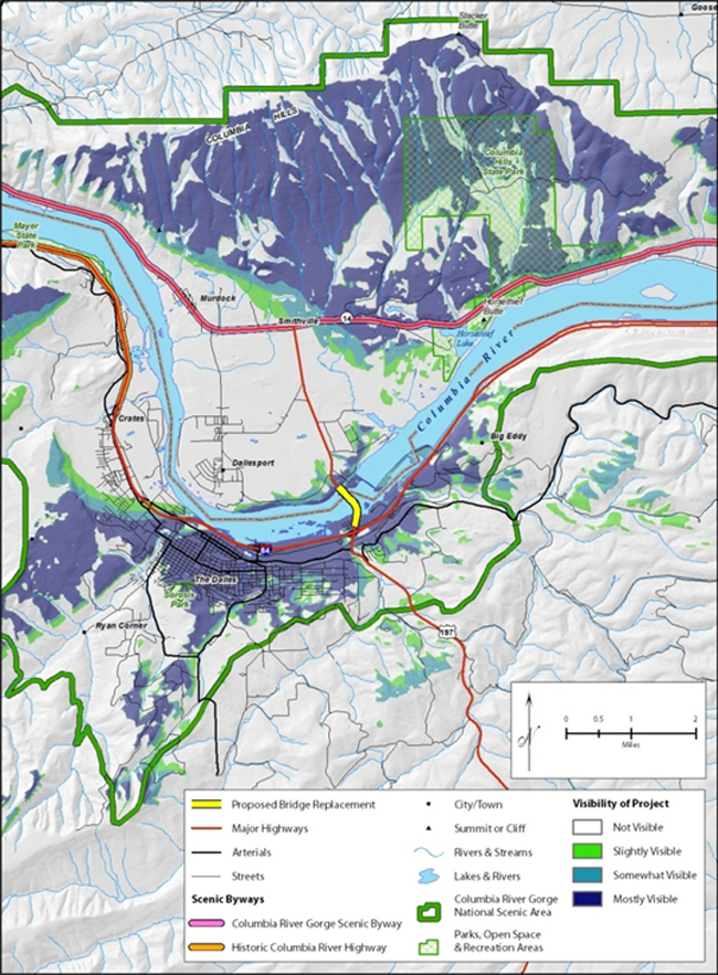
Figure 6-1. Example of a Distance Zone Map
This map is an example of a viewshed analysis which depicts the visibility of a proposed bridge that would affect the visual character of views from a National Scenic Area, two scenic byways, a State park, major highways, and urban areas.
Movement
Viewer sensitivity can also be affected by the movement of the viewer (see Figure 6-2, Dynamic Viewsheds and Speed). Movement creates dynamic views (see Dynamic Viewsheds in Section 4.4.2, Determine Viewsheds), affecting the sensitivity of travelers, especially drivers who concentrate on watching the road ahead. The faster a person moves the smaller the area on which they are able to focus their attention. At 25 mph, a driver can see a view approximately 100° wide; at 45 mph, the view drops to 65°; and at 65 mph, it drops to a narrow 40°, substantially reducing what is seen.
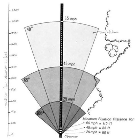
Figure 6-2. Dynamic Viewsheds and Speed
The viewshed of a traveler moving along a highway is also affected by speed. A viewshed decreases as speed increases.
Source: U. S. Bureau of Land Management. Visual Resource Management Program (Course 8400-05) 2008.
Authors should begin the task of assessing viewer sensitivity by reviewing the visual impacts made by the project in each landscape unit (Section 6.2.1, Assess Visual Compatibility) and reviewing the interests of the viewer groups affected by these changes (Section 5.3, Affected Population). You should identify how viewer exposure and viewer awareness will affect their sensitivity to the project’s visual impacts. Use Table 6-2: Viewer Sensitivity Matrix as a guide for analyzing and developing a narrative describing the sensitivity or insensitivity the viewers will have to the project’s visual impacts.
Table 6-2. Viewer Sensitivity Matrix
| |
Impacts on Natural Harmony |
Impacts on Cultural Order |
Impacts on Project Coherence |
| Viewer Exposure |
Proximity |
Are some viewers closer than others to the impacts? How are impacts affected by distance zones? Which impacts are particularly visible? Which impacts are the least visible? |
| Extent |
How many people, and who, are affected by the impacts? Which viewer groups are the most affected and why? Are some viewer groups unaffected? |
| Duration |
How lengthy are the viewing periods? Does the length of time viewing the impact lessen or increase the visibility of the impact to a particular viewer group? Which viewer groups are affected by dynamic views? How are they affected? |
| Viewer Awareness |
Attention |
For which viewer groups are the views in this corridor routine? For which are they unique? |
| Focus |
Is there a particular visual resource that is an iconic focal point or are views more general? |
| Protection |
Are there particular visual resources or features that are protected legally or by custom? |
| Use this table as a guide for writing a narrative about the sensitivity viewers have with the impacts that will be caused by the proposed project. |
By assessing the sensitivity of viewers to impacts by viewer group, a more robust understanding emerges of not only how sensitive a particular viewer group will be to changes in the dimensions of visual quality but why it is sensitive. Such a determination will later enable the project management team to better identify and mitigate adverse impacts and to incorporate beneficial impacts during the mitigation phase.
6.2.3 Assess Impacts to Visual Quality
Viewer sensitivity to the impacts to visual resources determines the degree of impacts to visual quality. Authors should define the degree of the impact as adverse, beneficial, or neutral. Begin the task of assessing impacts to visual quality by viewer group for each landscape unit. You should use Table 6-3: Impacts to Visual Quality Matrix to analyze and develop a narrative description of the impacts to visual quality.
Table 6-3. Impacts to Visual Quality Matrix
| |
Viewer Sensitivity |
| Exposure |
Awareness |
| Impacts to Visual Compatibility |
Natural Harmony |
How have changes in exposure and awareness affected the experience of natural harmony in the AVE? Have the changes caused by the project been adverse, beneficial, or neutral to the experience of natural harmony in the AVE? |
| Cultural Order |
How have changes in exposure and awareness affected the experience of cultural order in the AVE? Have the changes caused by the project been adverse, beneficial, or neutral to the experience of cultural order in the AVE? |
| Project Coherence |
How have changes in exposure and awareness affected the experience of project coherence in the AVE? Have the changes caused by the project been adverse, beneficial, or neutral to the experience of project coherence in the AVE? |
| Visual Quality |
How have changes in exposure and awareness affected the experience of overall visual quality in the AVE? Have the changes caused by the project been adverse, beneficial, or neutral to the experience of overall visual quality in the AVE? |
| Use this table as a guide for writing a narrative about the impacts the proposed project would have on the experience of visual quality by neighbors and travelers. Complete the assessment for each viewer group in each landscape unit. |
6.3 Document the Analysis Phase
Authors should use maps, a narrative description, and images to document the analysis phase.
Maps
Authors should use the map produced for the establishment phase of the AVE and its associated landscape units as a base. You should highlight and label impacts on the visual quality of the AVE, highlighting especially those areas where the proposed project will alter the harmony of the natural environment, the order of the cultural environment, or the coherence of the project environment. You should key the map to before images, after-project simulations, and the narrative. The details and complexity of maps will usually reflect the level of the document being produced—Abbreviated VIA, a Standard VIA, or an Expanded VIA. It is usually not necessary to produce a map for a project whose visual impacts are being assessed with a VIA Memorandum. See Appendix D for suggestions on what maps and figures to include in the VIA specific to each level of documentation.
Narrative Description
The descriptive narrative is the core of the VIA. It documents the analysis and explains if changes to the visual resources of the natural, cultural, and project environments are compatible or incompatible with existing visual resources. It also provides an analysis of whether and how the sensitivities of neighbors and travelers will be triggered by the changes wrought by proposed project. Finally, the analysis should answer whether the degree of impact to baseline visual quality will be adverse, beneficial, or neutral.
Images
Authors should use photographs or illustrations that depict the changes in visual quality that represent impacts. You should use computer simulations made from images taken at key views, if necessary, for complex or controversial projects. You should describe the impact in a caption. See Appendix F for information on how to create images of the existing scene and generate simulations of what will be proposed for a “before and after” comparison. These simulations provide a visual explanation of how the visual experience of visual quality will be altered by the proposed project.
Back to Top
In this Chapter:
- Mitigation types
- Effective mitigation
- Examples of mitigation
Chapter 7. Mitigation Phase
7.1 Introduction
Mitigation is the fourth phase of preparing a VIA. During this phase, recommend how to avoid, minimize, and compensate for significant adverse visual impacts associated with a transportation project and identify opportunities for enhancing visual quality.
NEPA requires consideration of mitigation to help lessen the overall impact of a project on the land and on people. As described under NEPA (40 CFR 1508.20), mitigation includes:
- Avoiding the impact altogether by not taking a certain action or parts of an action.
- Minimizing impacts by limiting the degree or magnitude of the action and its implementation.
- Rectifying the impact by repairing, rehabilitating, or restoring the affected environment.
- Reducing or eliminating the impact over time by preservation and maintenance operations during the life of the action.
- Compensating for the impact by replacing or providing substitute resources or environments.
Mitigation is used to address direct and indirect impacts. In some cases, mitigation can help create beneficial impacts. Conversely, mitigation may not fully rectify adverse impacts but may serve to lessen the overall effect of a project.
The goal of the VIA guidelines is to maintain or enhance existing visual quality. To achieve this, mitigation can act on the visual resources of the natural, cultural, or project environments or on the experience of viewers. Section 7.4 provides examples of mitigation, types of mitigation, and recommendations for developing effective mitigation.
7.2 Types of Mitigation
In order of preference, the three different methods for mitigating adverse impacts are: avoidance, minimization, and compensation.
- Avoidance. Authors should make reasonable efforts to avoid adverse impacts on visual resources, viewers, or visual quality to the extent that avoidance is feasible. Avoidance may mean selecting an alternative that does not incur the impact over ones that have the impact. If an alternative or avoidance measure does not also avoid or lessen other social, economic, or environmental impacts, it may not be selected. It is advisable to collaborate with other resources specialists to identify avoidance measures that could benefit other resource-types (e.g., noise) investigated in NEPA-related documents.
- Minimization. Alternatives and measures which minimize or reduce an adverse visual impact are preferred over alternatives that more fully impact the visual resource. Again, coordinating with other resource specialists is advantageous.
- Compensation. If it is not possible to avoid or minimize adverse impacts, it is essential that these impacts be compensated for through other actions, preferably within the project corridor. In order to maintain or enhance existing visual quality, compensation should contribute to visual quality to the same extent as the project detracts from it.
- Enhancement. Enhancements are opportunities for the project to improve existing visual quality by improvements to either visual resources or the experience of viewers. Visual resources can be enhanced by removing undesirable features or rehabilitating or adding desirable ones. To enhance the experience of viewers, measures can either limit undesirable views that currently exist or improve views of desirable features.
7.3 Effective Mitigation
Mitigation and enhancement measures should be technically possible and practical. They should be acceptable by the community and regulatory agencies as actually mitigating the adverse impacts identified by the VIA. Finally, mitigation measures should be politically and financially feasible to the community and organizations that will need to pay for their construction and maintenance. Authors should tailor mitigation and enhancement recommendations to the specific project. It may help to follow established processes, such as Context Sensitive Solutions or similar State DOT guidance when coordinating with the public and project designers to identify effective and acceptable mitigation.
7.3.1 Mitigation and Enhancement Development Process
Developing effective mitigation and enhancement measures involves: (1) identifying specific environments and visual resources affected by the project (natural, cultural, and project) and (2) identifying specific viewers and views affected by the project (travelers and neighbors). This is completed during the first three phases of the VIA process. Authors should review the findings and establish exactly what visual resources and whose views will be adversely impacted. Knowing this will allow mitigation and enhancement measures to be efficiently directed to addressing the impacts on specific resources and viewers. Next, you should determine whether mitigation measures can be created to avoid, minimize, or compensate for adverse impacts or if enhancement measures can be incorporated to create beneficial effects. Take care that the mitigation does not cause additional negative impacts. For example, if the only place to locate a berm or wall to screen views of a roadway facility from sensitive residential viewers would impact a threatened or endangered plant community, the value of preserving sensitive habitat would outweigh using that mitigation option. A matrix that can be used to help develop mitigation measures by impact type is included in Table 7-1. You should consider all potential mitigation and enhancement measures when developing a mitigation and enhancement plan for the project.
Table 7-1. Direction for Developing Mitigation Measures by Impact Type
| Impact Type |
Mitigation Measure Type |
Mitigation to act on: |
Environment
(Visual Resources of the Natural, Cultural, or Project Environments) |
Viewers
(Visual Experience of Travelers and Neighbors) |
| Adverse |
Avoidance |
Choose options that maintain the quantity and quality of existing visual resources |
Maintain existing views for all viewer groups |
| Minimization |
Choose option that does the least harm to existing visual resources |
Maintain to the largest extent possible existing views for most viewer groups |
| Compensation |
Replace adversely affected resource with the same type of resource |
Re-establish similar views of the same visual feature |
| Compensation |
Provide substitute for affected resource |
Create substitute views of similar visual features or other interesting features |
| Beneficial |
Enhancement |
- Remove degraded resources
- Rehabilitate degraded visual resources
- Add complementary visual resources to the natural, cultural, or project environments
|
- Screen undesirable views
- Create desirable views
|
7.3.2 Mitigation and Enhancement of the Natural Environment
The mitigation and enhancement of the natural environment typically focuses on impacts to topography, hydrology, and vegetation. Grading is a primary source of adverse impacts to topography. This includes a thorough investigation of alternative alignments, profiles, and cross-sections. Avoiding or minimizing changes to the existing topography or compensating for impacts by mimicking the visual character of the native landscape is crucial for mitigating adverse visual impacts. This is particularly true for grading embankments and creating rock cuts, which often require biotechnical measures (such as retaining walls and mesh fabrics) to stabilize slopes and prevent falling rocks. Working directly with highway geometric engineers to fit the roadway into the existing landscape can be extremely beneficial to mitigating impacts to the natural environment.
Avoiding or minimizing impacts to water bodies is similarly essential for visually integrating a roadway into the existing landscape. Mimicking the visual character, especially the alignment, cross-section and gradient of native streams and rivers or the shape of the perimeter and the form of the impoundment of native ponds and lakes is helpful in integrating the roadway and the natural environment.
How well adverse impacts to vegetation are mitigated often influences how the public judges a project’s impacts and an agency’s commitment to environmental stewardship. Mitigation of adverse impacts to vegetation starts with avoidance and frequently extends to compensation. Compensation needs to be sensitive to the context of the project. Picking the appropriate type and location for new vegetation is essential for the success of the mitigation measure. Typically, plantings can be informal, formal, or semi-formal depending on the highway’s environmental context.
7.3.3 Mitigation and Enhancement of the Cultural Environment
Highways can enhance cultural order for both neighbors and travelers if thoughtfully integrated with the pattern of society. Improvements in transportation systems can become a catalyst for improving the image of a community. Highway projects may impact cultural order by the design and placement of highway structures. The material, forms, and finishes of the structures of a highway should mimic, complement, or contrast with the existing cultural environment visible from the project corridor, as desired by the community.
To reduce impacts on a neighbor, avoid disrupting the pattern of the community. Especially avoid impacting the community’s cultural landmarks, particularly those that provide orientation. Sensitively integrate the highway into the community by the use of forms, materials, and finishes which reflect the image the community wishes to project. To reduce impacts for a traveler, the highway should be consistent with drivers’ expectations. If a highway fails to appear orderly, it feels uncomfortable and may seem less safe. The neatness of the community seen from the road is also important to a traveler. Neatness tells a traveler of how neighbors value their community and the people who pass through it.
Frequently, preferred forms, materials, and finishes can be accurately deduced from adjacent buildings and other structures. However, this can be misleading if not confirmed during the public involvement process. Although the existing cultural environment may provide hints of what is appropriate to mimic, only input from viewers can confirm what is actually visually important to a community.
7.3.4 Mitigation and Enhancement of the Project Environment
Adverse impacts to the highway environment can be mitigated by coordinating the appearance of the visual resources that compose the highway corridor. In particular creating a coherent composition by artistically coordinating the materials, forms, and finishes of bridges, retaining walls, and noise walls tends to be critical in mitigating adverse visual impacts. Coordinating other design elements, such as the design of sign supports, signs, lights, crash barriers, fences, pavements, traffic signals, corridor vegetation, community entrance markers, overlooks, and rest areas will further improve the composition of the corridor. Authors should develop a highway composition with input from the community.
7.4 Examples of Mitigation
The following examples of construction- and design-related mitigation measures are intended to aid in identifying mitigation options and a general range of effective mitigation measures for locations with significant visual impacts. Mitigation is not necessary for every project. The mitigation measures used depend on the visual impacts that result from the project. The first step in identifying measures is to reference standards and specifications already in place for use on the project sponsor’s projects, such as Construction Materials Specifications and the AASTHO Green Book. Existing specifications and guidance may cover the scenarios identified below. The mitigation measures here exist to fill gaps in existing specifications and guidance. Authors should tailor these examples to address specific project mitigation needs. For example, Mitigation Measure VIS-#: Limit construction to daylight hours may be revised to become Mitigation Measure VIS-#: Limit construction to daylight hours adjacent to residences or it may not be needed at all if there are no sensitive viewers in proximity to the project that would be affected by nighttime construction. Additional mitigation measures that are not included in these guidelines may also be needed, or may be better suited, to address project impacts. Note, verb usage in mitigation measure language is often prescribed by the particular project. As seen in the provided examples, mitigation measures vary in their use of shall and will.
7.4.1 Construction-Related Mitigation
The following measures can be used to mitigate temporary adverse impacts associated with construction.
Mitigation Measure VIS-#: Minimize fugitive light from portable sources used for construction
Scenario: Lighting from night time construction impacts surrounding neighborhoods.
Mitigation measure: At a minimum, the construction contractor shall minimize project-related light and glare to the maximum extent feasible, given safety considerations. Color-corrected halide lights will be used. Portable lights will be operated at the lowest allowable wattage and height and will be raised to a height no greater than 20 feet. All lights will be screened and directed downward toward work activities and away from the night sky and nearby residents to the maximum extent possible. The number of nighttime lights used will be minimized to the greatest extent possible.
Mitigation Measure VIS-#: Limit construction to daylight hours
Scenario: Land uses adjacent to the construction area have particular sensitivity to night time lighting.
Mitigation measure: Construction activities scheduled to occur after 6:00 p.m. or on weekends will not continue past daylight hours (which varies according to season). This would reduce the amount of construction experienced by viewer groups, because most construction activities would occur during business hours (when most viewer groups are likely at work), and eliminate the need to introduce high-wattage lighting sources to operate in the dark.
Mitigation Measure VIS-#: Restore staging areas once decommissioned
Scenario: Restoration of staging areas after project completion
Mitigation measure: The project proponent will restore staging areas to preconstruction conditions once the facilities are decommissioned and removed to minimize the impact on visual quality and character at these sites. Restoration of the decommissioned sites will meet the following performance standards. All disturbed terrain will be restored. Replacement plantings will be installed in areas where vegetation was removed. All replacement plantings will be native and indigenous to the area. No invasive plant species will be used under any conditions. Implementation of this measure will result in restoration of staging areas.
7.4.2 Examples of Design-Related Mitigation
The following measures are a few examples of best practices and methods to avoid or minimize adverse impacts associated with a project as part of the design process. For many projects, these considerations occur during the design process rather than during NEPA, but may result from input received on the project during the public involvement process. Combine, revise, and tailor these examples to meet project needs. As discussed above, many of these examples or similar approaches may be in the project proponent’s Construction Materials Specifications or in other design standards such as the AASHTO Green Book.
Mitigation Measure/Best Practice VIS-#: Underground new utilities
Scenario: Consider for locations where existing utilities are underground to fit the project into the surrounding context
Mitigation measure: Where feasible, the project sponsor will underground new utilities to minimize their visual intrusion upon the landscape. Undergrounding new utilities will not be used where implementation would constitute an adverse effect on sensitive habitats or sensitive species that would outweigh the reduction of visual effects.
Mitigation Measure/Best Practice VIS-#: Locate new transmission lines, and access routes to minimize the removal of trees and shrubs and pruning needed to accommodate new or relocated transmission lines
Scenario: The project proponent wants to minimize vegetation removal.
Mitigation measure: Site-specific location adjustments will be made by the design engineer to avoid adversely affecting mature tree and shrub groupings to the extent feasible and to avoid creating large, linear swaths of vegetation clearing. Where new or relocated transmission lines are located near trees along designated scenic route portions of [roadway name], the construction contractor will utilize selective pruning techniques to avoid hard pruning of tree canopies that would negatively affect those scenic resources and views along those routes. The project will evaluate using existing transmission corridors to accommodate new transmission lines to avoid the creation of new transmission corridors to the extent feasible.
Mitigation Measure/Best Practice VIS-#: Minimize the removal of trees and shrubs and pruning needed to accommodate new or reconstructed noise barriers
Scenario: The project requires construction or replacement of noise barriers adjacent to the right-of-way line.
Mitigation measure: Clear brush and neatly trim and/or remove trees in conflict with the proposed noise barrier locations. Remove only those trees that are necessary to perform the work. Obtain approval from the project engineer prior to removing any ornamental trees. Carefully perform trimming to avoid harming trees and hindering future growth. Mark all trees scheduled to be trimmed or removed and obtain approval from the project engineer prior to performing the work. For clarification, trees shall be interpreted as any growth with a minimum trunk diameter of 3”.
Mitigation Measure/Best Practice VIS-#: Compensate affected parcel owners for landscaping and landscape features removed or damaged during construction
Scenario: Project construction results in vegetation removal or damage to adjacent property owners.
Mitigation measure: The sponsor will compensate, where appropriate and to the degree possible, parcel owners for landscaping, fencing, privacy walls, mailboxes, and other similar features damaged due to project construction. Replacement would be of value at least equal to that of existing features. To determine compensation for trees, an arborist certified in appraising a tree for the value it adds to that property will be used to determine monetary compensation for removal of that tree at such locations. Similarly, a person(s) qualified in evaluating landscape features other than trees, such as fencing, privacy walls, or other similar features, for the cost of replacement will be used to determine compensation for loss of features at such locations. The results of the assessment of private-property tree and landscape features will be used to determine the budget needed to implement this mitigation measure and will be included in the costs to construct as part of the proposed project. Before final project acceptance, funding source(s) for replacement of these features will be in place.
Mitigation Measure/Best Practice VIS-#: Replace landscaping, fencing, privacy walls, and other similar features for private properties to the degree possible
Scenario: Project construction results in vegetation removal or damage to adjacent property owners.
Mitigation measure: Where appropriate and to the degree possible, landscaping and related appurtenances, fencing, privacy walls, and other similar features removed from private property by construction must be replaced or restored in place and in kind to mitigate for visual impacts resulting from the loss of such features. For the purpose of traffic safety, replacement of removed features will only occur outside the clear recovery zone. The Project Engineer or a designated representative will be responsible for identifying and inventorying plant material anticipated for removal.
Mitigation Measure/Best Practice VIS-#: Design contours to mimic natural terrain
Scenario: The project requires site grading
Mitigation measure: Contour grading that looks like natural terrain to the degree possible would lessen visual impacts by creating a more natural landform. Consider using excess fill to create berms to shield adjacent properties from the highway.
Mitigation Measure/Best Practice VIS-#: Use native grass and wildflower species in erosion control grassland seed mix
Scenario: Erosion control with native vegetation
Mitigation measure: The project sponsor will require construction contractors to incorporate native grass and wildflower seed to standard seed mixes, which may be non-native, for erosion control measures applied to exposed slopes. Use native wildflower and grass species in the seed mix, and prohibit use of any invasive grass or wildflower plant species as a component in erosion control measures. Choose species indigenous to the area and that are appropriate to the surrounding habitat. For example, choose upland grass and wildflower species for drier, upland areas, and choose wetter species for areas that will receive more moisture. Limit use of wildflower seed mix to locations where appropriate to the surrounding habitat.
Mitigation Measure/Best Practice VIS-#: Implement roadside (or project) landscaping
Scenario: The project includes landscaping
Mitigation measure: Design the project in a manner that incorporates attractive [roadside] landscaping. Landscaping serves as a buffer and screens nuisance lighting resulting from oncoming vehicle headlights and roadway lighting and helps prevent or reduce nuisance lighting from affecting private properties. Prior to approval of the roadway design, the sponsor will review project designs to ensure implementation of the following elements in the project landscaping plan where feasible:
- One hundred percent of the species composition will reflect species that are native and indigenous to the Plan Area and [state name]. Native plant species can be used to create attractive spaces, high in aesthetic quality, that are not only drought-tolerant but attract more wildlife than traditional landscape plant palettes. Use of native species promotes a visual character of [state name] that is being lost through development and reliance on non-native ornamental plant species.
- The species list will include trees, shrubs, and an herbaceous understory of varying heights, as well as both evergreen and deciduous types. Plant variety will increase the effectiveness of the roadside planting areas by providing multiple layers, seasonality, diverse habitat, and reduced susceptibility to disease.
- Special attention should be paid to plant choices near rural residences to ensure that species chosen are of an appropriate height and rely on evergreen species to provide year-round light screening from nuisance light.
- Under no circumstances will any invasive plant species be used at any location.
- Vegetation will be planted within the first six months following project completion.
- An irrigation and maintenance program will be implemented during the plant establishment period and carried on, as needed, to ensure plant survival. However, design of the landscaping plan will try to maximize the use of planting zones that are water efficient. The design may also incorporate aesthetic features, such as a cobbling swales or shallow detention areas, which can reduce or eliminate the need for irrigation in certain areas.
- If an irrigation system is required, areas that are irrigated will use a smart watering system that evaluates the existing site conditions and plant material against weather conditions to avoid overwatering of such areas. To avoid undue water flows, the irrigation system will be managed in such a manner that any broken spray heads, pipes, or other components are fixed within 1-2 days, or the zone or system will be shut down until it can be repaired.
Mitigation Measure/Best Practice VIS-#: Apply aesthetic design treatments to visible structures
Scenario: Use of aesthetic design treatments on structures
Mitigation measure: Design structures associated with the proposed project in a manner that allows these features to blend with the surrounding built and natural environments so that they complement the visual landscape. Such measures will include, but are not limited to, the following:
- Aesthetic treatments to structures will be implemented to help soften their visual intrusion upon the landscape, especially in areas of high use, to improve project aesthetics.
- Structures will be constructed with low-sheen and non-reflective surface materials to reduce potential for glare. Unpainted metal surfaces will not be permitted.
- At a minimum, finishes will be matte and roughened and concrete [insert structure] will be painted or will use concrete colored integrally with a shade that is two to three shades darker than the general surrounding area. Choose colors from the Federal Color Standard 595. All paints used for the color panels and structures will be color matched directly from the physical color chart, rather than from any digital or color-reproduced versions of the color chart. Paints will be of a dull, flat, or satin finish only to reduce potential for glare, and the use of glossy paints for surfaces will be avoided. Appropriate paint type will be selected for the finished structures to ensure long-term durability of the painted surfaces. The appropriate operating agency or organization will maintain the paint color over time.
Mitigation Measure/Best Practice VIS-#: Apply aesthetic treatments to the design of bridges and grade-separated crossings over roadways
Scenario: Use of aesthetic design treatments on structures
Mitigation measure: The design will evaluate historic and well-designed rail and road bridges in the area to develop a designs for bridges and grade-separated crossings that complement the natural landscape, are aesthetically pleasing, and minimize the effects of visual intrusion upon the landscape.
Paint new structures with a shade that is 1 to 2 degrees darker than the general surrounding area to create less of a visual impact on the surrounding landscape. Choose colors from Federal Color Standard 595.
All paints used for the color panels and structures will be color matched directly from the physical color chart and not any digital or color reproduced versions of the color chart. Limit paints to those with dull, flat, or satin finish. Select appropriate paint type for the finished structures to ensure long term durability of the painted surfaces. The project proponent will maintain the paint color over time.
Concrete or shotcrete structures will implement aesthetic design features such as mimicking natural material (e.g., stone or rock surfacing) and integral color to reduce visibility and to blend better with the landscape.
Designs using lattice steel structures will be evaluated for grade-separated crossings for trails. Such a structure would be less visually confining than a tunnel, provide better visual access to points beyond, allow light to travel through the structure, and may appear less like a visual barrier to recreationists using the trail.
Mitigation Measure/Best Practice VIS-#: Construct walls and barriers with aesthetic treatments and low-sheen and non-reflective surface materials
Scenario: Use of aesthetic design treatments on structures
Mitigation measure: Include aesthetic treatments on retaining walls and noise barriers. The objective of these treatments is to reduce the appearance of the wall surface by blending better with the surroundings. Colors and aesthetics should be appropriate for the location where they are built (i.e., a more formal wall treatment should be applied near a commercial area, while a more natural-looking wall treatment should be applied in areas where there are no residences or businesses). These walls and barriers should have low-sheen and non-reflective surface materials to reduce potential for glare, which may limit use of some types of anti-graffiti protection. Wall finishes should be matte and roughened. Avoid smooth trowelled surfaces and glossy paint.
Mitigation Measure/Best Practice VIS-#: Implement retaining wall aesthetics
Scenario: Use of aesthetic design treatments on structures
Mitigation measure: A roughened wall surface softens the verticality of the wall face by providing visual texture and reducing the amount of smooth surface that can reflect light. Choosing earth-toned colors for the wall surface is less distracting to viewers and helps the wall blend with the planted vegetation as it matures. Adding a design motif to the wall face that reflects natural materials reduces visual monotony, softens verticality, and is more pleasing to viewers than a plain wall surface. Furthermore, , plantable wall surfaces, such as a retaining wall structure with interstices for planting will be evaluated for use as a possible best management practice to limit graffiti. Do not use a plantable wall surfaces if it requires more space and create a greater impact to the community.
Careful selection of the color and shade of the wall is necessary to select colors and shades that complement the surrounding landscape. Light colors, such as buff/tan, brown, or gray stand out more than darker colors such as deep browns, deep red-browns, and deep warm grays vegetation.
Mitigation Measure/Best Practice VIS-#: Apply minimum lighting standards
Scenario: Best practices for low impact project lighting
Mitigation measure: Limit artificial outdoor lighting to safety and security requirements and designed using Illuminating Engineering Society’s design guidelines and in compliance with International Dark-Sky Association approved fixtures. Lighting should provide minimum impact to the surrounding environment utilize downcast, cut-off type fixtures that are shielded and direct the light only towards objects requiring illumination. Install lights at the lowest allowable height and cast low-angle illumination while minimizing incidental light spill onto adjacent properties, open spaces, or backscatter into the nighttime sky. Utilize the lowest allowable wattage for all lighted areas and minimize the amount of nighttime lights needed to light an area as much as possible. Light fixtures will have non-glare finishes that will not cause reflective daytime glare. Design all lighting to maximize energy efficiency, safety and security, and to be aesthetically pleasing.
Mitigation Measure/Best Practice VIS-#: Evaluate need for safety lighting
Scenario: Best practices for low impact project lighting
Mitigation measure: Evaluate the need for safety lighting near underpasses and in the newly created cul-de-sacs in Landscape Unit X. Install lights in accordance with Mitigation Measure VIS-#, Apply minimum lighting standards, employing aesthetic light treatments to the extent feasible.
Back to Top
Appendix A Glossary
Affected Environment: As defined by NEPA, this is the “environment of the area(s) to be affected or created by the alternatives under consideration” (40 CFR 1502.15).
Area of Visual Effect (AVE): The area in which views of the project would be visible as influenced by the presence or absence of intervening topography, vegetation, and structures.
Background: The zone that extends from 3-5 miles to infinity miles away from the viewer.
Baseline Conditions: Existing conditions of the affected environment, affected population, and existing visual quality.
Color: The light reflecting off of an object at a particular wavelength that creates hue (green, indigo, purple, red, etc.) and value (light to dark hues). (U.S. Bureau of Land Management 1980:15; Federal Highway Administration 1988:40).
Cumulative Impacts: Impact on the environment which results from the incremental impact of the action when added to other past, present, and reasonably foreseeable future actions. Cumulative impacts can result from individually minor but collectively significant actions taking place over a period of time. (Sec. 1508.7)
Direct Impacts: Impacts caused by the action and occur at the same time and place. (Sec. 1508.8a)
Distance Zones: Distance zones are based on the position of the viewer in relationship to the landscape. They are measured from one static point, such as the location of a key view. There are three defined distance zones:
- Foreground: 0.25-0.5 mile from the viewer
- Middleground: Extends from the foreground zone to 3-5 miles from the viewer
- Background: Extends from the middleground zone to infinity (Litton 1968).
Equivalent Focal Length: The zoom length needed for a digital SLR to have the same zoom length as a 35mm film camera.
Foreground: The zone that extends from the viewer to 0.25-0.5 mile away from the viewer.
Form: The unified mass or shape of an object that often has an edge or outline and can be defined by surrounding space. For example, a high-rise building would have a highly regular, rectangular form whereas a hill would have an organic, mounded form. (U.S. Bureau of Land Management 1980:15; Federal Highway Administration 1988:40).
Impact: Change. Change can be made to the physical environment (measured by the compatibility of the impact) or to viewers (measured by sensitivity to the impacts). Together, the compatibility of the impact and the sensitivity of the impact yield the value of the impact to visual quality.
- Compatibility of the Impact: Defined as the ability of environment to visually absorb the proposed project as a result of the project and the environment having compatible visual characters. The proposed project can be considered compatible or incompatible. By itself, compatibility of the impact should not be confused or conflated with the value of the impact.
- Sensitivity to the Impact: Defined by the ability of viewers to see and care about a project’s impacts. The sensitivity to impact is based on viewer sensitivity to changes in the visual character of visual resources. Viewers are either sensitive or insensitive to impacts. By itself, the sensitivity of the impact should not be confused or conflated with the value of the impact.
- Value of the Impact: Defined as either a beneficial, adverse, or neutral change to visual quality. A proposed project may benefit visual quality by either enhancing visual resources or by creating better views of those resources and improving the experience of visual quality by viewers. Similarly it may adversely affect visual quality by degrading visual resources or obstructing or altering desired views.
Indirect Impacts: Impacts caused by the action and are later in time or farther removed in distance, but are still reasonably foreseeable. Indirect impacts may include growth inducing effects and other effects related to induced changes in the pattern of land use, population density or growth rate, and related effects on air and water and other natural systems, including ecosystems. (Sec. 1508.8b)
Key View: A location from which a viewer (traveler or neighbor) can see either iconic or representative landscapes, with or without the highway, of the project corridor. Usually there is at least one key view for each landscape unit. Used for visual simulations.
Landscape Units: Defined areas within the AVE that have similar visual features and homogeneous visual character and frequently, a single viewshed. An “outdoor room.” Typically the spatial unit used for assessing visual impacts.
Line: Perceived when there is a change in form, color, or texture and where the eye generally follows this pathway because of the visual contrast. For example, a city’s high-rises can be seen silhouetted against the blue sky and be seen as a skyline, a river can have a curvilinear line as it passes through a landscape, or a hedgerow can create a line where it is seen rising up against a flat agricultural field. (U.S. Bureau of Land Management 1980:15; Federal Highway Administration 1988:40)
Middleground: The zone that extends from 0.25-0.5 mile to 3-5 miles away from the viewer.
Permanent Impacts: Impacts resulting from construction activities lasting for 2 or more years, the built project, or the operations and maintenance associated with the built project.
Project Region: The 30-mile radius surrounding a project corridor.
Project Vicinity: The 0.5-mile offset surrounding a project corridor.
Protected Visual Resources: Components of the natural, cultural, or project environments that are capable of being seen and that are protected under local, state, or federal plans or policies. There are instances where there is an overwhelming community interest in the preservation of the aesthetic qualities of visual resources that although they are not officially protected by local, state, or federal plans or policies, they still warrant protection.
Temporary Impacts: Impacts resulting from construction or short-term activities that fall within a period of 2 years or less.
Threshold of Impact: The limits or bounds used to assess impacts. Impacts can be adverse or beneficial.
Simulations: Two or three dimensional depictions of the visual character of a future state. Simulations range from artistic renderings to computer animations.
Texture: The perceived coarseness of a surface that is created by the light and shadow relationship over the surface of an object. For example, a rough surface texture (e.g., a rocky mountainside) would have many facets resulting in a number of areas in light and shadow and, often, with distinct separations between areas of light and shadow. Conversely, a smooth surface texture (e.g., a beach) would have fewer facets, larger surface areas in light or shadow, and gradual gradations between light and shadow. (U.S. Bureau of Land Management 1980:15; Federal Highway Administration 1988:40).
Viewers: Neighbors who can see the proposed project and travelers who would use it.
- Neighbors: Viewers who occupy or will occupy land adjacent or visible to the proposed project. For a complex or controversial project, neighbors can be defined by land-use, including: residential, retail, commercial, industrial, agricultural, recreational, and civic neighbors.
- Travelers: Viewers who use the existing or would use the proposed transportation project. For complex or controversial projects, travelers can be defined by the purpose of traveling, including: commuting, hauling, touring, or exercising travelers; or by their mode of travel as motorists, bicyclists, or pedestrians.
Viewer Sensitivity: The degree to which viewers are sensitive to changes in the visual character of visual resources. It is the consequence of two factors, viewer exposure and viewer awareness.
- Viewer Exposure: Viewer exposure is a measure of proximity (the distance between viewer and the visual resource being viewed), extent (the number of viewers viewing), and duration (how long of a time visual resources are viewed). The greater the exposure, the more viewers will be concerned about visual impacts.
- Viewer Awareness: Viewer awareness is a measure of attention (level of observation based on routine and familiarity), focus (level of concentration), and protection (legal and social constraints on the use of visual resources). The greater the attention, the more viewers will be concerned about visual impacts.
Viewshed: All of the surface area visible from a particular location (e.g., an overlook) or sequence of locations (e.g., a roadway or trail) (Federal Highway Administration 1988: pp. 26-27)
Visual Character: The description of the visible attributes of a scene or object typically using artistic terms such as form, line, color, and texture.
Visual Impacts: Changes to visual resources, viewers, or visual quality.
Visual Quality: What viewers like and dislike about visual resources that compose the visual character of a particular scene. Different viewers may evaluate specific visual resources differently based on their interests in natural harmony, cultural order, and project coherence. Neighbors and travelers may, in particular, have different opinions on what they like and dislike about a scene.
- Natural Harmony: What viewer likes and dislikes about the natural environment. The viewer labels the visual resources of the natural environment as being either harmonious or inharmonious. Harmony is considered desirable; disharmony is undesirable.
- Cultural Order: What a viewer likes and dislikes about the cultural environment. The viewer labels the visual resources of the cultural environment as being either orderly or disorderly. Orderly is considered desirable; disorderly is undesirable.
- Project Coherence: What the viewer likes and dislikes about the project environment. The viewer labels the visual resources of the project environment as being either coherent or incoherent. Coherent is considered desirable; incoherent is undesirable.
Visual Resources: Components of the natural, cultural, or project environments which are capable of being seen.
- Natural Visual Resources: The land, water, vegetation, and animals which compose the natural environment. Although natural resources may have been altered or imported by people, resources which are primarily geological or biological in origin are considered natural. A grassy pasture with rolling terrain, scattered trees, and grazing cows, for example, is considered to be composed of natural visual resources, even though it is a landscape created by people.
- Cultural Visual Resources: The buildings, structures, and artifacts which compose the cultural environment. These are resources which were constructed by people.
- Project Visual Resources: For highway transportation projects, the geometrics, structures, and fixtures which compose the project environment. These are the constructed resources which were or will be placed in the environment as part of the proposed project.
Back to Top
Appendix B. References
American Society of Civil Engineers, 1976. Highway Esthetics.
Appleton, Jay, 1975. The Experience of Landscape. William Clowes & Sons, Ltd. London. Appleton draws from John Dewey’s Experience and Nature, 1929 and Art as Experience, 1934 to state on page 48 of his book: “Dewey’s main message, for our purposes, is that beauty resides neither intrinsically in ’beautiful’ objects nor in ’the eye of the beholder’, but that it is to be discovered in the relationship [emphasis added] between the individual and his environment, in short in what he calls ’experience’.” Recent scientific studies, such as Landscape Depiction and Perception: A Transactional Approach (Zonn, Leo E.) have confirmed the notion that visual perception-and therefore the perception of visual quality-are the result of this process of transactional perception.
Congressional Research Service. 2013. National Monuments and the Antiquities Act, Congressional Research Service Report for Congress (7-5700, R41330). Available: https://coast.noaa.gov/data/Documents/OceanLawSearch/Congressional Research Service, National Monuments and the Antiquities Act (July 20, 2010).pdf. Accessed: July 11, 2013.
Duton, Denis, 2009. The Art Instinct: beauty, pleasure, and human evolution. Bloomsbury Press, New York.
Federal Highway Administration. 1995. FHWA Docket No. 95-15: National Scenic Byways, Notice of FHWA Interim Policy. USDOT. May 18, 1995.
---. 1988. Visual Impact Assessment for Highway Projects. (FHWA-HI-88-054.) USDOT (US Department of Transportation), 1988.
FHWA (Federal Highway Administration). 2013a. Section 4(f) Program Overview Available: https://www.environment.fhwa.dot.gov/legislation/section4f.aspx. Accessed: July 3, 2013.
--2013b. Section 4(f) Policy Paper. Available: https://www.environment.fhwa.dot.gov/legislation/section4f/4fpolicy.aspx. Last updated: July 20, 2012. Accessed: July 3, 2013.
ICF International. 2013. Visual Impact Assessment Guidelines-Survey Results Analysis. Final. March. (ICF 112801.0.007.) Fairfax, VA. Prepared for FHWA, Washington, DC.
Jones, Grant R., David F. Sorey, and Charles G. Scott, 2007. Applying Visual Resource Management Assessment for Highway Planning, in Landscape Architectural Graphic Standards. Leonard J. Hopper, editor. John Wiley & Sons, Hoboken, New Jersey.
Litton, R. Burton, Jr. 1968. Forest Landscape Description and Inventories – A Basis for Land Planning and Design. (U.S. Department of Agriculture Forest Service Research Paper PSW-49) Pacific Southwest Forest and Range Experiment Station. Berkeley, CA. 1968.
Minnesota Department of Transportation, 2010. Highway Project Development Process, Scoping, Subject Guidelines, Visual Impact Assessment. Available: https://dot.mn.gov/project-development/subject-guidance/visual-quality/process.html. Last updated: August 25, 2010. Accessed: June 28, 2013.
National Park Service. 2013. National Trails System, General Information, Frequently Asked Questions. Available: https://www.nps.gov/subjects/nationaltrailssystem/faqs.htm. Last updated: March 18, 2013. Accessed: June 14, 2013.
NEPA (National Environmental Policy Act). 2013. State Environmental Planning Information. Last updated: February 14, 2013. Accessed: June 18, 2013.
Panero, J. and M. Zelnik. 1979. Human Dimension & Interior Space: A Source Book of Design Reference Standards. New York, NY: Whitney Library of Design.
Scenic America, 2004. Symposium on Scenic Conservation: Public Agency Practice. June 9-10, 2004, River Farm, Alexandria, VA.
Churchward, Craig, James F. Palmer, Joan Iverson Nassauer, and Carys Anne Swanwick. 2013. NCHRP Report 741 Evaluation of Methodologies for Visual Impact Assessments. Washington, DC: National Cooperative Highway Research Program, Transportation Research Board, National Academy of Sciences.
U. S. Bureau of Land Management. 2008. Visual Resource Management Program (Course 8400-05).
U.S. Forest Service, 1995. Landscape Aesthetics: A Handbook for Scenery Management. Rev.ed., Agricultural Handbook 701. Washington, D.C.: U.S. Department of Agriculture.
Zonn, Leo E. “Landscape Depiction and Perception: A Transactional Approach.” Landscape Journal. September 21, 1984 3:144-150.
Back to Top
Appendix C. VIA Scoping Questionnaire
The following ten questions can be used to determine the appropriate level of effort for assessing the impacts on visual quality that may result from a proposed highway project. The first set of five questions is concerned with environmental compatibility impacts on the visual resources of the affected environment. The second set of five questions deals with the sensitivity of the affected population of viewers to those impacts.
Consider each of the ten questions on the questionnaire and select the response that most closely applies to the project in question. Each response has a corresponding point value. After the questionnaire is completed the total score will represent the type of VIA document suitable for the project.
It is important that this scoring system be used as a preliminary guide only. Although these questions provide some guidelines for determining if a VIA is necessary, it should not, by itself, be considered definitive. If there is any hint that visual issues may be a factor in assessing impacts, it is recommended that a VIA be conducted. Although the total score will direct the user toward a particular level of VIA documentation, circumstances may necessitate selecting a different level of analysis and documentation based on previous experience, local concerns, or professional judgment. This checklist is meant to assist the writer of the VIA to understand the degree and breadth of the possible visual issues. The goal is to develop an analysis and document strategy that is appropriately thorough, efficient, and defensible.
Visual Impact Assessment Scoping Questionnaire
| Project Name: |
|
Site Visit Date: Day, 00/00/0000 |
| Location: |
|
Time: 0:00 a.m. / p.m. |
| Special Conditions/Notes: |
|
Conducted By: |
Environmental Compatibility
1. Will the project result in a noticeable change in the physical characteristics of the existing environment?
(Consider all project components and construction impacts - both permanent and temporary, including landform changes, structures, noise barriers, vegetation removal, railing, signage, and contractor activities.)
 High level of permanent change (3) High level of permanent change (3) |
Moderate level of permanent change (2) |
| Low level of permanent or temporary change (1) |
No Noticeable Change (0) |
2. Will the project complement or contrast with the visual character desired by the community?
(Evaluate the scale and extent of the project features compared to the surrounding scale of the community. Is the project likely to give an urban appearance to an existing rural or suburban community? Do you anticipate that the change will be viewed by the public as positive or negative? Research planning documents, or talk with local planners and community representatives to understand the type of visual environment local residents envision for their community.)
| Low Compatibility (3) |
Moderate Compatibility (2) |
| High compatibility (1) |
|
3. What level of local concern is there for the types of project features (e.g., bridge structures, large excavations, sound barriers, or median planting removal) and construction impacts that are proposed?
(Certain project improvements can be of special interest to local citizens, causing a heightened level of public concern, and requiring a more focused visual analysis.)
| High concern (3) |
Moderate concern (2) |
| Low concern (1) |
Negligible Project Features (0) |
4. Is it anticipated that to mitigate visual impacts, it may be necessary to develop extensive or novel mitigation strategies to avoid, minimize, or compensate for adverse impacts or will using conventional mitigation strategies, such as landscape or architectural treatment adequately mitigate adverse visual impacts?
| Extensive Non-Conventional Mitigation Likely (3) |
Some non-conventional Mitigation Likely (2) |
| Only Conventional Mitigation Likely (1) |
No Mitigation Likely (0) |
5. Will this project, when seen collectively with other projects, result in an aggregate adverse change (cumulative impacts) in overall visual quality or character?
(Identify any projects [both state and local] in the area that have been constructed in recent years and those currently planned for future construction. The window of time and the extent of area applicable to possible cumulative impacts should be based on a reasonable anticipation of the viewing public’s perception.)
| Cumulative Impacts likely: 0-5 years (3) |
Cumulative Impacts likely: 6-10 years (2) |
| Cumulative Impacts unlikely (1) |
|
Viewer Sensitivity
1. What is the potential that the project proposal may be controversial within the community, or opposed by any organized group?
(This can be researched initially by talking with the state DOT and local agency management and staff familiar with the affected community’s sentiments as evidenced by past projects and/or current information.)
| High Potential (3) |
Moderate Potential (2) |
| Low Potential (1) |
No Potential (0) |
2. How sensitive are potential viewer-groups likely to be regarding visible changes proposed by the project?
(Consider among other factors the number of viewers within the group, probable viewer expectations, activities, viewing duration, and orientation. The expected viewer sensitivity level may be scoped by applying professional judgment, and by soliciting information from other DOT staff, local agencies and community representatives familiar with the affected community’s sentiments and demonstrated concerns.)
| High Sensitivity (3) |
Moderate Sensitivity (2) |
| Low Sensitivity (1) |
|
3. To what degree does the project’s aesthetic approach appear to be consistent with applicable laws, ordinances, regulations, policies or standards?
| Low Compatibility (3) |
Moderate Compatibility (2) |
| High compatibility (1) |
|
4. Are permits going to be required by outside regulatory agencies (i.e., Federal, State, or local)?
(Permit requirements can have an unintended consequence on the visual environment. Anticipated permits, as well as specific permit requirements - which are defined by the permitter, may be determined by talking with the project environmental planner and project engineer. Note: coordinate with the state DOT representative responsible for obtaining the permit prior to communicating directly with any permitting agency. Permits that may benefit from additional analysis include permits that may result in visible built features, such as infiltration basins or devices under a storm water permit or a retaining wall for wetland avoidance or permits for work in sensitive areas such as coastal development permits or on Federal lands, such as impacts to Wild and Scenic Rivers.)
5. Will the project sponsor or public benefit from a more detailed visual analysis in order to help reach consensus on a course of action to address potential visual impacts?
(Consider the proposed project features, possible visual impacts, and probable mitigation recommendations.)
Determining the Level of Visual Impact Assessment
Total the scores of the answers to all ten questions on the Visual Impact Assessment Scoping Questionnaire. Use the total score from the questionnaire as an indicator of the appropriate level of VIA to perform for the project. Confirm that the level suggested by the checklist is consistent with the project teams’ professional judgments. If there remains doubt about whether a VIA needs to be completed, it may be prudent to conduct an Abbreviated VIA. If there remains doubt about the level of the VIA, begin with the simpler VIA process. If visual impacts emerge as a more substantial concern than anticipated, the level of VIA documentation can always be increased.
The level of the VIA can initially be based on the following ranges of total scores:
Score 25-30
An Expanded VIA is probably necessary. It is recommended that it should be proceeded by a formal visual scoping study prior to beginning the VIA to alert the project team to potential highly adverse impacts and to develop new project alternatives to avoid those impacts. These technical studies will likely receive state-wide, even national, public review. Extensive use of visual simulations and a comprehensive public involvement program would be typical.
Score 20-24
A Standard VIA is recommended. This technical study will likely receive extensive local, perhaps state-wide, public review. It would typically include several visual simulations. It would also include a thorough examination of public planning and policy documents supplemented with a direct public engagement processes to determine visual preferences.
Score 15-19
An Abbreviated VIA would briefly describe project features, impacts and mitigation requirements. Visual simulations would be optional. An Abbreviated VIA would receive little direct public interest beyond a summary of its findings in the project’s environmental documents. Visual preferences would be based on observation and review of planning and policy documents by local jurisdictions.
Score 10-14
A VIA Memorandum addressing minor visual issues that indicates the nature of the limited impacts and any necessary mitigation strategies that should be implemented would likely be sufficient along with an explanation of why no formal analysis is required.
Score 6-9
No noticeable physical changes to the environment are proposed and no further analysis is required. Print out a copy of this completed questionnaire for your project file to document that there is no effect. A VIA Memorandum may be used to document that there is no effect and to explain the approach used for the determination.
Back to Top
Appendix D. Types of VIA Documents
When it is determined that a VIA is needed, there are four distinct possible levels of reporting. Help to determine the appropriate level of VIA document is provided in Chapter 3 of the VIA Guidelines. These four levels, listed by increasing complexity, are:
- VIA Memorandum
- Abbreviated VIA
- Standard VIA
- Expanded VIA
Basic descriptions of each level of VIA document are described in this Appendix.
VIA Memorandum
A VIA Memorandum is simply a short memorandum from the VIA author to the NEPA project manager stating that the potential for the project to cause adverse or beneficial impacts to visual resources, viewers, or visual quality is negligible and explaining the approach used to reach that conclusion. A VIA Memorandum is usually reserved for projects that are Categorical Exclusions (CEs) but may include Environmental Assessment (EA) or Environmental Impact Statement (EIS)-level projects with little or no visual impacts.
Abbreviated VIA
An Abbreviated VIA is a document that succinctly reports the findings of a VIA. It includes a brief project description and a report of the findings of the VIA’s establishment, inventory, analysis, and mitigation phases. Maps, aerial photography and photographs are used sparingly and only when such illustrations reduce the need for text. An Abbreviated VIA is typically used for an EA or EIS-level project when it has been identified during scoping that there are minimal visual concerns. It may also be used for CEs, if a VIA Memorandum will not suffice and a slightly more detailed analysis is needed to address visual impacts.
To report the establishment phase, identify the location and extent of the project corridor on a map, along with the area of visual effect. Provide a brief project description. Typically, for an Abbreviated VIA, it is not necessary to delineate viewsheds or landscape units.
To report the inventory phase, briefly identify visual resources of the natural, cultural, and project environments as a description of the visual character of the project corridor; briefly identify the viewing experience of neighbors and travelers; and finally, identify existing visual quality as what viewers like and dislike about the existing environment.
To report the analysis phase, define how the visual character of the corridor will change as a result of the project. Describe impacts to visual resources and the experience of viewers. Define the degree of impacts as being beneficial, adverse, or neutral.
To report the mitigation phase, describe how mitigation strategies avoid, minimize, or compensate for adverse visual impacts and how beneficial visual impacts will be incorporated in the project.
Standard VIA
A Standard VIA would typically be used for EA or EIS projects that are anticipated as having substantial adverse or beneficial visual impacts. In the Standard VIA document, report the findings of the establishment, inventory, analysis, and mitigation phases of the VIA process. The Standard VIA is developed with input from the NEPA public involvement process to directly and accurately ascertain viewer preferences. It is suggested that these findings be presented in a manner more traditional with how environmental review documents are produced by presenting the findings in the following chapters:
Chapter 1: Project Description. Report the project’s purpose and need and identify issues of visual quality. Define and map the project location. Provide a project description, including descriptions of alternatives and any associated plans or cross-sections, as appropriate.
Chapter 2: Methodology. Describe the purpose of the VIA and how it will be used to inform location, design, and mitigation decisions of the transportation agency. Describe the assessment methodology, noting the use of the FHWA VIA guidelines and any modifications to the methodology recommended in the guidelines. The VIA Flow Chart (see Figure 3-1 in the guidelines) can be inserted into the document to illustrate the process, if preferred.
Chapter 3: Affected Environment. Describe the regulatory setting, listing any federal, state, or local laws, rules, ordinances, or other regulations that are related to visual issues, visual resources, visual character, visual quality, or the visual experience of viewers. Define and map the area of visual effect, and show the location of distinct landscape units and associated key views.
Provide representative images and descriptions of the visual character of the landscape units, identifying in particular the visual resources of the natural, cultural, and project environments.
Describe the visual character of project. These descriptions can be documented by landscape units, if the visual character of the project in each landscape unit is unique.
Briefly describe who are the neighbors and travelers, their self-interest, their sensitivity to visual change, and their visual preferences.
Define existing visual quality by identifying viewer’s impressions of existing visual character, especially their impressions of natural harmony, cultural order, and project coherence.
Chapter 4: Impact Analysis and Mitigation. Describe how the proposed project will alter the visual character of the area of visual effect and consequently the experience of visual quality by viewers. Define the impacts to visual quality using the concepts of changes to natural harmony, cultural order, and project coherence.
Describe in common language the visual impacts to natural harmony, cultural order, and project coherence. Discuss this in terms of the compatibility or incompatibility of the visual character of the proposed project with the visual character which currently exists in the area of visual effect and how visual quality would be affected. Discuss how key views would be affected. Use before and after images to illustrate impacts, in cases where simulations are used. Provide a narrative discussion with the simulations discussing how they relate to the public’s viewer preferences. Describe the expected viewer sensitivity to these changes. Define impacts as being adverse, beneficial, or neutral. Describe any anticipated cumulative impacts to existing visual quality associated with the project.
Suggest how to avoid, minimize, or compensate for adverse impacts and how to incorporate beneficial impacts into the project as enhancements. Recognize that mitigation and enhancements can affect either visual resources or viewers, as noted in Chapter 7.
Expanded VIA
An Expanded VIA is usually reserved for very complex or controversial projects where resolving visual issues has been identified as being key to public acceptance of a project. To report an Expanded VIA, follow the same outline as a Standard VIA, except report findings with more detail. In particular, the inventory of Landscape Units and Viewers Groups may be more fine-grained, rendering more subtlety in defining existing visual quality and impacts to it. For an Expanded VIA, alternative alignments or alternative designs may be fully and separately inventoried and analyzed. For an Expanded VIA, utilizing an effective public participation strategy to accurately ascertain viewer preferences is key for determining impacts to visual quality and designing effective mitigation strategies. Provide a description of how the public was involved in the VIA process. The development of simulations showing impacts and mitigation is especially necessary for reporting the findings of an Expanded VIA.
Back to Top
Appendix E. Field Reconnaissance Techniques
Use the following information to prepare for and conduct a field reconnaissance trip.
What to Bring
Bring field maps that may include aerial imagery or screen shots of internet satellite mapping so that these can be used to mark photo locations or to take notes upon. It is also helpful if the aerial mapping has an overlay of the project’s design plans or, at a minimum, the project boundaries. If this information cannot be overlain, then taking a set of the design plans in the field is beneficial.
While a digital point and shoot camera will suffice, a digital single lens reflex (SLR) is the preferred tool for shooting images to be used in the VIA document. It is preferable that the digital SLR can capture images in “JPEG Normal” mode. A camera-mounted GPS is helpful in capturing key view locations. This may include using a stand-alone GPS unit that will store point data or a camera mounted GPS unit that will geotag the images as they are taken.
A polarizer attached to the camera lens protects the lens and cuts down on atmospheric haze captured in the image. Generally, once the polarizer is in place, most people shooting photography tend to leave it in place and only take it off to replace the filter if it is damaged or for thorough lens cleanings.
A lens hood will prevent light entering from the side of the lens, reduce or eliminate light flares captured on the image, allow for higher color quality, and limit image washout on brighter days. If a lens hood is unavailable, cupping a hand around the right or left side of the lens, depending on the direction of the sun, helps to reduce washout. If using this technique, be sure to pay attention and ensure the hand is kept out of the frame. Note that on overcast days, shooting with a lens hood may not be preferable. Shoot some images with and without a lens hood and evaluate the results to determine when to forgo using the lens hood.
It is also helpful to have a vehicle navigation system or smart phone with a GPS mapping program for finding alternate routes. Be aware of safety concerns at the project site and of potentially hazardous site conditions. Never take risks while accessing a project site or the areas surrounding it and always notify someone of the details of the site visits (e.g., location, estimated time of return). Dress appropriately for weather conditions and have food and water, if needed. In addition, use a vehicle that is appropriate for accessing the AVE.
During the Visit
Visit the key view locations and photograph these locations to document the presence or absence of views of the sites. Additional locations can be surveyed and photo documented by driving the roads surrounding the project site to capture the most descriptive views down the roadway corridors and toward the project site at intersections or where a safe road pull-out is present along longer or winding roadways with direct views toward the sites.
Here are some basic shooting guidelines.
- Ensure that the date and time stamps are correct.
- If a camera-mounted GPS is being used, ensure that it is attached and working before beginning the visit.
- Manual or auto-focus may be used. Auto-focus may result in slight inaccuracies in panorama shots as the camera focuses on the changing foreground when panning. However, auto-focus is often used to limit the number of blurry images due to human error.
- Set the camera to the 50mm equivalent focal length (zoom). This configuration is the de facto standard that approximates the average view cone and magnification of the human eye. However, the size of the area exposed by a 35mm film camera is 36 × 24 mm while the size of the area exposed by a digital SLR is smaller. Therefore, refer to the digital SLR manual to find out the dimensions of the camera’s picture size so that the 50mm equivalent focal length can be calculated. Below is an example.
- The picture size of the digital SLR is 23.6 × 15.8 mm. Therefore, a film camera is approximately 1.5 times (36 ÷ 23.6 = 1.5 or 24 ÷ 15.8 = 1.5) larger than the digital SLR.
- To calculate the approximate equivalent focal length of lenses for the digital SLR in 35mm format, multiply the focal length of the lens by 1.5. So, if the zoom is set to 50mm on the digital SLR, the image captured is actually what would be seen at 75mm (50 × 1.5 = 75) on film.
- Therefore, to get a 50mm zoom on the digital SLR, divide by 1.5 (50 ÷ 1.5 = 33 mm). Setting the zoom to 35mm, which is a standard zoom length, would work well for taking pictures during the site visit.
- While most pictures should be shot using the 50mm equivalent focal length, zooming in, to capture more detail, and out, to capture more of the surrounding landscape, can be helpful. Figure F-1 includes a helpful hint on marking the camera lens with the 50mm equivalent focal length.
- Candidate key views and simulated key views are often documented in a 360° view to gain an understanding of available views from the perspective of both motorists and surrounding viewers and to understand the visual setting. Single views can be captured as well, but keep in mind that it is always best to have too many photos than not enough. This makes the most of the field visit and provides more photos to review once back in the office.
- Overlap each photo by at least 1/3rd while shooting from left to right. This will allow enough image overlap to create panoramas.
- Keep the camera straight and pivot on the ground point, staying on that point as closely as possible. Avoid shifting the camera angle up or down when rotating to prevent uneven image overlap. If the camera cannot be held steady, use a tripod when shooting for simulations.
- Do not use a flash. When shooting for low-light or nighttime conditions use a tripod and cable release for best results at the required slow shutter speeds. Take the camera out of auto-focus mode and shoot manually for these lighting conditions. General experience in manual photography is needed for these conditions.
Figure F-1. Lens Marked with 50mm Equivalent
Photos for simulations should be shot using a 50mm equivalent focal length. REMEMBER that not all digital SLRs are the same. The 50mm equivalent will need to be calculated for the camera. After identifying the 50mm equivalent, use a paint pen or magic marker to put a permanent mark or dot on the lens so that it can be found easily in the field. This is indicated by the green dot in the image above. The pink dot represents the range that can be zoomed to for images that are key views.
After the Visit
Back up images at the end of each field day. It is good practice to download the images onto a computer hard drive, USB, or other storage device. If the memory card becomes accidentally damaged or destroyed before it can be transferred to a network, valuable time, budget, and data may be lost.
It is also helpful to organize the images. This is often done by vantage point location or location name. This will help during the writing process when views need to be evaluated from a certain location or representative photographs need to be chosen to accompany the VIA text descriptions.
Back to Top
Appendix F. Photo Simulations
Producing accurate photo simulations requires basic camera operation skills and proficiency in working with the software, images, and project design plans. Because photo simulations become a part of the public record, inaccurate or low-quality graphic work could result in potential issues for a project. Low-quality simulations could also result in wasted time and budget if simulations need to be recreated. Additional sources with helpful information for shooting for simulations include:
Photography-related Equipment for Photo Simulations
It is preferable to use a digital SLR with resolution greater than 10 megapixels and that can capture images in “JPEG Normal + RAW” or “JPEG Normal + NEFf1” mode. This dual-capture setting produces a JPEG image for general use when preparing the VIA and a high quality electronic image data file that is the equivalent of a film negative. Similar to a film negative, the RAW/NEF file can be used to create a JPEG without losing any original data and captures the fine details of the subject, making the RAW/NEF file the optimum format for use in creating simulations. If the camera does not have RAW capabilities, use the highest image quality available on the camera, such as the “Fine” setting. Using the highest image quality setting on your camera translates to fewer images that can be stored on the memory card. Some point and shoot cameras will not provide adequate image quality for simulations. A camera-mounted GPS or GPS capable equipment should be used to document the location of the vantage point being used for the photo simulation.
Optional equipment includes a tripod, cable release, and a compass. A tripod is helpful for shooting in a fixed location to achieve steady and even panning when shooting panoramas and should be used with a cable release in low-light conditions at slow shutter speeds to avoid camera shake. A compass may be helpful for establishing shots and recording the direction of the vantage being shot.
Simulation-related Software
Graphic designers and CAD/GIS technicians often aid in the preparation of visual simulations. A variety of software and techniques are used to assess the visibility of project features and to demonstrate changes in views as a result of proposed projects. This software is used to develop and manipulate three-dimensional (3D) models, integrate those models with photographs of existing conditions, and then prepare reliable and informative computer-generated photo simulations.
Information Needed
Preparation of photo simulations requires information and data used to digitally and graphically construct the proposed visual changes. The following information is useful in helping to locate existing and proposed features in the landscape:
- Site design plans that include layout mapping and provide existing and proposed topographical lines; demolition plans; the location and elevation of existing structures; the location and elevation of proposed roadways, bridges, and other built features; and stockpile and staging areas at a scale of 1:2,000 or less.
- Arborist report, including proposed tree removal or limits of vegetation removal, if available.
- Site design landscaping and lighting plans.
- Aerial photographs showing land uses and environmental concerns within 500 feet of the project site at a scale of 1:2,000 or less.
- 3D model of existing and proposed structures.
- Material and color themes for any proposed structures or project features.
Establishing Locations
Prior to establishing locations for photo simulations, evaluate the project’s design plans and have a general understanding of site conditions. Often, project budget can only accommodate a limited number of simulations so evaluate the site, viewers present, and the project design and decide which location(s) would provide the greatest benefit in simulating. The location and view should be representative of the project site and potential for impact. Establishing locations for photo simulations generally follows these steps:
- Evaluate the site using internet satellite mapping to get a sense of where viewers are located and how the site currently looks. This will start to provide a sense of where the most direct or obscured views of the project are located.
- Determine if there are sensitive visual resources such as scenic roadways or designated Wild and Scenic Rivers.
- Evaluate project design plans to have a solid understanding of what is proposed to happen where at the project site.
- Research any scoping issues raised by the public over concerns for visual resources. Begin to think about what the range of visual impacts will be. Gain a general sense of where the worst-case project impacts are likely to occur.
- Coordinate with the client and project management team to find out if there are any predetermined locations that have been selected for simulating. Preparing up-front, and completing steps 1 through 4 above will allow for a useful dialogue with the project team.
- If budget allows, a viewshed analysis using GIS can help to provide additional information on if views are available from specific locations (Section 4.4, Define the Area of Visual Effect). This is particularly helpful in areas with more topographical relief. Steps 1 through 5 will help to determine which locations should be analyzed.
- Have a general idea about which locations might work well for simulating.
- Visit the site to “truth” (verify) these locations. Shoot these locations using the camera settings needed for simulating. Visit other locations with views of the site. If other locations turn up that were not considered before, also shoot these locations using the camera settings needed for simulating.
- Back in the office, evaluate all the potential simulation location options and weigh the benefits of using one location over another. Here are some questions to ask:
- Which views represent the greatest impact to the greatest number of representative viewers?
- Do the views represent the cross section of viewers exposed to the site? For example, if three simulations can be prepared for a project and there are views from a park, residential areas, commercial areas, and the roadway, it may not make sense to simulate only views from the affected residential areas. A better approach might be to simulate views from the park, a location in the residential area, and one from either the roadway or the commercial area. This would provide a wider representation of project impacts.
- Are there any views that should be simulated to show there would be minimal impacts? Oftentimes, locations for simulations tend to reveal themselves once there is a better understanding of the project, the project site, and affected viewers.
- Have the person preparing the simulations evaluate the design plans and images shot at locations for project features with alternate locations to determine if any alternate locations can be eliminated.
- Run the selected locations past the project’s management team and, if possible, the public, to refine locations and to get approval on final locations for simulating.
Photo Simulation Methodology Text
Photo simulations are used to assess project impacts. Include a description of the methodology used to produce photo simulations in the VIA document. The followingf2 is provided only as an example of photo simulation methodology. Tailor the actual description—including noting the software and equipment used—to the project.
“Images were photographed using a >10 megapixel digital single lens reflex camera equipped with a 50-millimeter equivalent focal length lens. This configuration is the de facto standard that approximates the proportion seen by the human eye. The camera positioning was determined with a sub-meter differentially corrected GPS.
The visual simulations provide clear before- and after- images of the location, scale, and visual appearance of the features affected by and associated with the proposed project and its alternatives. The simulations were developed through an objective analytical and computer modeling process and are accurate within the constraints of the available site and alternative data (three-dimensional computer model was created using a combination of AutoCAD files and geographic information system [GIS] layers and exported to Autodesk’s 3-dimensional Studio Max for production). Design data—engineering drawings, elevations and cross sections, site and topographical contour plans, concept diagrams, and reference pictures—were used as a platform from which digital models were created. In cases where detailed design data were unavailable, more general descriptions about alternative facilities and their locations were used to prepare the digital models.”
Back to Top
Tips for Describing Landscapes Effectively
To describe landscapes effectively, use synonyms to replace the terms form, line, element, and texture. For instance, “the line of the river is meandering” is not as effective as “the meandering river”. Similarly, “A patchwork of row crops, pastureland, and apple orchards comprises the landscape” is more effective than “There are many rectangular fields that are adjacent to one another. Some of these fields look smoother because they are pasturelands planted with grasses that form a continuous vegetative cover, and there are some fields look rougher because orchards are planted with trees that have a rough appearance.” The second description causes the reader to become more focused on overly specific details whereas the first description paints a clear visual image of the landscape in the reader’s mind.
Appendix G. Visual Character Terminology
The basic components used to describe visual character of the natural, cultural, and project environments are the elements of form, line, color, and texture of the landscape features (USDA Forest Service 1995:28-34, 1-2-1-15, 3-3-3-13, 4-5; Federal Highway Administration 1988:37-43). The appearance of the landscape is described in terms of the dominance of each of these components. Examples of terminology to describe these components are provided in Table G-1.
Table G-1. Terminology for Visual Character Components
Back to Top
Appendix H. Prepared Statements for Environmental Documents
Authors of a project’s environmental documents could use one of these four statements for transferring the findings of a VIA into a project’s draft and final environmental documents. These statements standardize terms and the order in which information is presented. These prepared statements respond to the four types of NEPA findings of effect: (1) no impacts on visual quality, (2) adverse impacts on visual quality, (3) no adverse impacts on visual quality, and (4) beneficial impacts on visual quality.
No Impacts on Visual Quality
This statement is an example of text that could be used for projects that have no impacts, adverse or beneficial, on visual quality.
“No impact on the visual resources of the natural, cultural, and project environments is anticipated. No impact on the ability of the affected population to view visual resources is anticipated. Visual quality will, therefore, not be altered by the proposed project. The proposed project will have no adverse impacts on visual quality nor will it create any opportunities to enhance visual quality in the project area. No mitigation is necessary.”
Adverse Impacts on Visual Quality
This statement is an example that could be used for projects that have adverse impacts on visual quality. This is a series of paragraphs beginning with a discussion of adverse impacts on visual resources, followed by a discussion of adverse impacts on viewers, and concluding with a discussion of mitigation and enhancement measures.
“The proposed project will create adverse impacts on visual quality by causing (minor or major) changes to the visual resources of the (natural, cultural, or project) environments). (List particular resources that will be adversely impacted)”
“The proposed project will create adverse impacts on visual quality by adversely affecting the sensitivity of (neighbors or travelers). (List specific adverse impacts on viewer exposure or awareness)”
“The proposed project will mitigate (avoid, minimize, or compensate for) adverse impacts on (natural, cultural, or project) visual resources and adverse impacts on the (exposure or awareness) of viewers. It will (list specific mitigation practices.)”
“The proposed project will enhance visual quality by removing undesirable (inharmonious, disorderly, or incoherent) visual resources; by rehabilitating formerly desirable (harmonious, orderly, or coherent) visual resources that are in disrepair; (and, or) by adding desirable (harmonious, orderly, or coherent) visual resources. It will enhance visual quality by (list specific enhancements.)”
No Adverse Impacts on Visual Quality
This statement is an example that could be used for projects that have no adverse impacts on visual quality.
“The proposed project will not create adverse impacts on visual quality. (No, or Only minor) adverse changes to the (natural, cultural, or project) environments are anticipated. (List minor impacts to visual resources, if any.) (No, or Only minor) adverse changes to viewer exposure or awareness are anticipated. (List minor impacts to viewers, if any.) (There are no, or These minor changes would not constitute) adverse impacts, therefore no mitigation is necessary.”
Beneficial Impacts on Visual Quality
This statement is an example that could be used for projects that have beneficial impacts on visual quality. It is composed of two paragraphs, one about enhancements to visual resources; the other about enhancements to viewer exposure and awareness.
“The proposed project will enhance visual quality by removing undesirable (inharmonious, disorderly, or incoherent) visual resources; by rehabilitating formerly desirable (harmonious, orderly, or coherent) visual resources that are in disrepair; (and, or) by adding desirable (harmonious, orderly, or coherent) visual resources. It will enhance visual quality by (list specific enhancements.)”
“The proposed project will enhance visual quality by limiting exposure to and awareness of undesirable (inharmonious, disorderly, or incoherent) views or by improving exposure to and awareness of desirable (harmonious, orderly, or coherent) views. It will (list specific enhancements.)”
Back to Top
Endnotes
1 Appleyard, Donald, Kevin Lynch, and John R. Myer. The View from the Road. Cambridge, MA; MIT Press, 1964.
2 NEPA, 1969. 42 U.S.C.USC § 4331.
3 Jones, Grant R., David F. Sorey, and Charles G. Scott, 2007. Applying Visual Resource Management Assessment for Highway Planning, in Landscape Architectural Graphic Standards. Leonard J. Hopper, editor. John Wiley & Sons, Hoboken, New Jersey.
4 Federal Highway Administration, 1988. Visual Impact Assessment for Highway Projects. (FHWA-HI-88-054.) USDOT (US Department of Transportation), 1988, reprinted 1990. (other various editions 1979-1990)
5 Minnesota Department of Transportation, 2010. Highway Project Development Process, Scoping, Subject Guidelines, Visual Impact Assessment. Available: https://dot.mn.gov/project-development/subject-guidance/visual-quality/process.html. Last updated: August 25, 2010. Accessed: June 28, 2013.
6 U.S. Forest Service, 1995. Landscape Aesthetics: A Handbook for Scenery Management. Rev.ed., Agricultural Handbook 701. Washington, DC: U.S. Department of Agriculture.
7 Scenic America, 2004. Symposium on Scenic Conservation: Public Agency Practice. June 9-10, 2004, River Farm, Alexandria, VA.
8 Transportation Research Board. 2013. Evaluation of Methodologies for Visual Impact Assessment. National Cooperative Highway Research Program Report 741. Washington, D.C. 2013.
9 Federal Highway Administration. 1995. FHWA Docket No. 95-15: National Scenic Byways, Notice of FHWA Interim Policy. USDOT. May 18, 1995.
10 National Park Service. 2013. National Trails System, General Information, Frequently Asked Questions. Available: https://www.nps.gov/subjects/nationaltrailssystem/faqs.htm. Last updated: March 18, 2013. Accessed: June 14, 2013.
11 Congressional Research Service. 2013. National Monuments and the Antiquities Act, Congressional Research Service Report for Congress (7-5700, R41330). Available: https://crsreports.congress.gov/product/pdf/R/R41330/30. Accessed: July 11, 2013.
12 FHWA (Federal Highway Administration). 2013a. Section 4(f) Program Overview Available: https://www.environment.fhwa.dot.gov/legislation/section4f.aspx. Accessed: July 3, 2013.
13 NEPA (National Environmental Policy Act). 2013. State Environmental Planning Information. Available: https://ceq.doe.gov/laws-regulations/states.html. Last updated: February 14, 2013. Accessed: June 18, 2013.
14 American Society of Civil Engineers, Highway Esthetics. 1976.
15 Dutton, Denis. The Art of Instinct: Beauty, Pleasure, and Human Evolution. Bloomsbury Press, New York. 2009.
16 Litton, R. Burton, Jr. 1968. Forest Landscape Description and Inventories - A Basis for Land Planning and Design. (U.S. Department of Agriculture Forest Service Research Paper PSW-49) Pacific Southwest Forest and Range Experiment Station. Berkeley, CA. 1968.
17 Litton, R. Burton, Jr. 1968. Forest Landscape Description and Inventories - A Basis for Land Planning and Design. (U.S. Department of Agriculture Forest Service Research Paper PSW-49) Pacific Southwest Forest and Range Experiment Station. Berkeley, CA. 1968.
18 Litton, R. Burton, Jr. 1968. Forest Landscape Description and Inventories - A Basis for Land Planning and Design. (U.S. Department of Agriculture Forest Service Research Paper PSW-49) Pacific Southwest Forest and Range Experiment Station. Berkeley, CA. 1968.
f1 NEF is the Nikon® equivalent of a RAW file
f2 Text courtesy of ICF International
Back to Top

