Stormwater Best Management Practices in an Ultra-Urban Setting: Selection and Monitoring
Fact Sheet - Underground Sand Filters
The underground sand filter typically consists of a multi-chamber underground vault accessible by access holes or grate openings. Multiple configurations have been developed for underground sand filters including the D.C. filter design (Figure 12) and the Delaware filter design (Figure 13). The D.C. design is intended to treat flow conveyed by a storm drain, and can be retrofitted within existing systems. The Delaware filter design is intended to collect flow directly from an impervious area and is well suited to placement along parking areas. While their deployments may differ, both of these designs operate in basically the same manner.
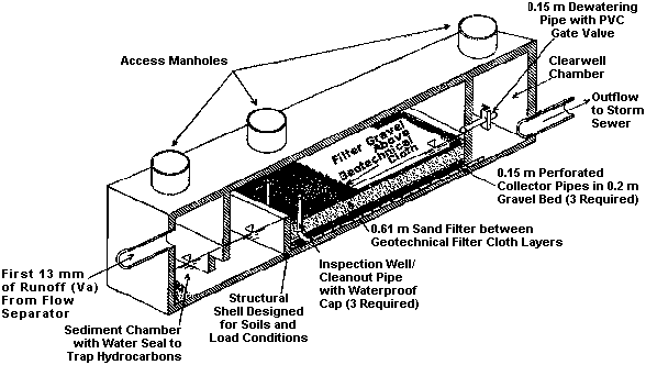
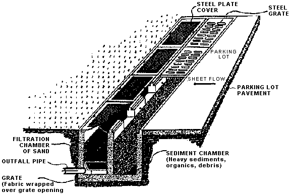
During a storm, the water quality volume is temporarily stored in an underground chamber(s) that provides for pretreatment by settling. Over time the stored volume flows by gravity into a filter chamber where it moves through the sand filter. Filtered runoff is collected in underdrains and is then discharged into an adjacent storm drain or natural channel. During large rainfall events any flow in excess of the filter's capacity is diverted around the sand filter by means of an overflow weir.
The underground sand filter works by a combination of sedimentation and filtration. The sedimentation section serves as a pretreatment measure by removing larger diameter suspended solids and capturing floating hydrocarbons. If the filter consists of a 45.7 cm (18 in) layer of sand the filter will trap up to 90 percent of the small particles in stormwater runoff (diameters between 6 to 41 microns). A lower level of removal will occur for any dissolved pollutants because the sand medium adsorbs relatively small amounts of positively charged dissolved materials. For example, sand has a cation exchange capacity that is 13 percent that of soil and 0.002 percent that of peat. This means it is less effective in filtering and removing dissolved metals and hydrocarbons.
Often the intended use of sand filter BMPs is to manage the first flush, which typically contains the highest concentration of pollutants. If designed as an off-line facility, however, it can provide true capture and treatment of any water quality volume. However, designers should note that it is relatively expensive to install large structures (e.g., concrete vaults) below grade and between any existing subsurface utilities.
In summary, the underground sand filter is well adapted for applications with limited land area and provides turnkey performance that is independent of local soil conditions, groundwater levels, and other factors. It is most useful where multiple uses of land area are required (i.e., where committed land area is to be used for automobile parking or for public parks).
Applicability
The underground sand filter is considered to be highly applicable to the ultra-urban setting. It requires a small commitment of land area, provides dependable service, and is relatively effective at urban pollutant removal. Its design is inherently flexible; the size and shape of the unit can be set based on local constraints. Because the unit is below grade, it is safe for application in public areas and is relatively vandal-proof. For roadside applications, it can be placed adjacent to roadways without imposing a safety hazard and can function satisfactorily in the area below elevated roadways or ramps. The effective life of a typical, maintained underground sand filter is 5 to 20 years.
If there is a disadvantage associated with underground sand filters, it is the relative expense of construction compared to surface BMPs like detention ponds. However, recognizing the premium for space in the ultra-urban environment, the underground filter is actually cost-effective and sometimes may be the only feasible alternative.
Effectiveness
Underground sand filters can be designed to effectively treat a range of target water quality volumes (e.g., the first 12.7 mm [0.5 in] runoff of a storm). The design water quality volume may be established by available space constraints, hydraulic conditions, or by local stormwater ordinances. Performance of this BMP is not greatly affected by climate since its subsurface placement will be below the frost line in most locations, limiting freezing of the filter. In addition, the level of treatment is generally independent of placement and on-site soil conditions do not affect performance. For larger-than-design events, underground sand filters (on-line and off-line) will only provide partial treatment. Pretreatment options such as streetsweeping or catch basins remove trash and accumulated sand from roadway sanding, both of which diminish a filter's operational performance and increase maintenance requirements.
The underground sand filter has demonstrated good total suspended solids (TSS) removals, typically providing 85 percent treatment. Effectiveness for nutrient removal is low, and in fact the sand filter may be a source of nitrate (NO3) since ammonia in stormwater will undergo nitrification in an aerobic filter environment. Trace metal removal rates range from between 65 and 95 percent. Removal of oil and grease averages about 80 percent with influent concentrations of 20 ppm and below. Reductions in fecal coliform bacteria range from between 40 and 80 percent. See Table 12 for additional information on the effectiveness of underground sand filters.
The sand filter is most effective in managing suspended solids but has questionable benefit where downstream conditions are sensitive to loadings of nitrogen or where high loadings of hydrocarbon pollutants are expected. Anions such as chloride from salted roadways are not removed during sand filtration.
Siting and Design Considerations
The flexible design of an underground sand filter permits a variety of applications. A first test of the feasibility of an application can be based on the space requirements for 12.7 mm (0.5 in) of runoff from an impervious area of 0.4 ha (1 ac). Using an assumed storage depth of 0.9 m (3 ft), the surface area requirement for a sand filter is approximately 14 m2 (150 ft2) for the sediment chamber and 18.6 m2 (200 ft2) for the sand filter area. More detailed design information can be found in Design of Stormwater Filtering Systems (Claytor and Schueler, 1996) and Evaluation and Management of Highway Runoff Water Quality (Young et al., 1996).
In the final design the key components are the sedimentation chamber that is usually a 0.92 m (3 ft) permanent pool depth and the filter bed that is typically 45.7 to 61 cm (18 to 24 in) deep. A maximum residence time of 40 hours is generally applied to ensure the sand filter drains prior to subsequent rainfall events. The total hydraulic drop from inlet to outlet should be between 1.5 and 2.4 m (5 and 8 ft) to reduce the potential for backwater flow into the sand filter from the downstream outlet. If the filter discharges to an existing storm drain, it is recommended that the underdrain outlet pipe drain into the top half of the downstream storm drain. The main collector pipe should be constructed with a minimum slope of 0.5 percent, and observation/inspection ports and cleanouts must be incorporated for all pipes. Access must be provided to all chambers in the design, and the design must conform to standards established by OSHA for worker safety.
Underground sand filters consist of precast or cast-in-place concrete vaults and can be installed as on-line or off-line facilities. Off-line applications are generally simpler to design because a high-flow bypass is not required and there is less potential for backwater flow entering the facility. During construction no runoff should enter the sand filter bed until the upstream drainage area is completely stabilized and site construction is completed. If practical, a sedimentation basin may serve as a temporary sediment control basin during site construction with the provision that overflows will bypass the filter bed. It is recommended that underground sand filters located in areas with sensitive groundwater aquifers be tested for water tightness prior to placement of the filter layers.
Maintenance Considerations
The recommended frequency for performance monitoring is four times per year. Each inspection should log information on the depth of ponding and oil and grease in the first chamber, the depth of water over the sand medium, and the accumulation of material over the sand medium. Any standing water over the sand medium 40 hours after the cessation of rainfall is indicative of clogging. Silt accumulation of more than 12.7 mm (0.5 in) indicates the need for replacement of the top layer or all of the sand medium. Typical sand media replacement intervals are from one to three years (Claytor and Schueler, 1996).
The sand filter design can be modified to minimize the effort associated with maintenance. For example, incorporating a plastic filter cloth covered with a gravel layer (ballast) on top of the sand medium creates a sacrificial layer that can be easily replaced when clogging occurs.
Currently, there are limited data on the expected maintenance costs associated with subsurface sand filters. A Washington, D.C., underground sand filter serving a 0.4 ha (1 ac) area was serviced by removal and replacement of a gravel ballast and filter cloth, for $1300 in 1994 (Bell, 1996). Note that repair of subsurface sand filters requires confined space entry, which requires larger management crews, leading to higher repair costs.
Preparations must be made for disposing of fluids and sediment removed from underground sand filters. Captured fluids may have a high hydrocarbon fraction and require special handling, and if the sand filter medium is not regularly replaced pollutants such as metals may accumulate in the sediment to the point where their level is considered hazardous.
Cost Considerations
Underground sand filters are generally considered to be a high-cost BMP option for water quality management. In 1994, the construction cost per impervious hectare served was $24,700 to $34,600 (or $10,000 to $14,000 per impervious acre served), excluding real estate, design, and contingency costs (Schueler, 1994). (Note that this unit cost value should be used for conceptual cost estimating purposes only.) In ultra-urban areas where land costs are high, however, underground sand filters can represent significant cost savings in reduced land consumption. For small ultra-urban areas with no land available, they may be the only practical option for stormwater quality treatment as they can be placed under roads or parking lots.
At this time manufacturers are beginning to make available prefabricated units that include precast vaults and inlets delivered to the site either partially or fully assembled. These units will eventually result in a decrease in construction costs. Typical significant cost variables include the location of subsurface utilities; type of lids and doors; customizing casting of weirs, sections, or holes; and depth of the vault.
References
Bell, W. 1996. BMP Technologies for Ultra-Urban Settings. In Proceedings of Effective Land Management for Reduced Environmental Impact, Tidewater's Land Management Conference on Water Quality, August 22, 1996.
Bell, W., L. Stokes, L.J. Gavan, and T. Nguyen. 1995. Assessment of the Pollutant Removal Efficiencies of Delaware Sand Filter BMPs. City of Alexandria, Department of Transportation and Environmental Services, Alexandria, VA.
Claytor, R.A., and T.R. Schueler. 1996. Design of Stormwater Filtering Systems. The Center for Watershed Protection, Silver Spring, MD.
Horner, R.R., and C.R. Horner. 1995. Design, Construction, and Evaluation of a Sand Filter Stormwater Treatment System. Part II: Performance Monitoring. Report to Alaska Marine Lines, Seattle, WA.
Schueler, T.R. 1994. Developments in Sand Filter Technology to Improve Stormwater Runoff Quality. Watershed Protection Techniques 1(2):47-54.
Young, G.K., S. Stein, P. Cole, T. Kammer, F. Graziano, and F. Bank. 1996. Evaluation and Management of Highway Runoff Water Quality. FHWA-PD-96-032. Federal Highway Administration, Office of Environment and Planning.
|

