Roadside Revegetation: An Integrated Approach to Establishing Native Plants and Pollinator Habitat
Chapter 5 – Implementation
Table of Contents
Back to top
5.1 INTRODUCTION
A successful revegetation project involves not only good planning but effective implementation of the plan. The Initiation Phase of this report (Chapter 2) described the organizations, decision processes, and technical concepts involved in beginning a roadside revegetation project. The Planning Phase chapter (Chapter 3) outlined the steps in the revegetation planning process resulting in a revegetation plan. This chapter details how the revegetation plan is translated into action at the project site.
The shift from the planning phase to the implementation phase involves a change in approach, and often, personnel. The planning process tends to be orderly and systematic, with the design team able to take an idealized bird’s-eye perspective of how the project might best proceed. In contrast, an implementation approach that is flexible and adaptable can help ensure the objectives of the plan are fulfilled while working with the sometimes-unpredictable nature of construction.
The tasks necessary to successfully implement a revegetation plan are:
- Developing contracts
- Developing an implementation schedule
- Maintaining a materials inventory
- Reviewing plans and coordinating with project engineer
- Assisting in implementing contracts
This chapter provides an overview of the implementation process, providing details on the key factors to consider, including soil and site treatments, obtaining plant materials, installing plant materials, and caring for plants after they have been installed.
5.1.1 DEVELOPING CONTRACTS
Revegetation tasks can be performed in-house, by agency personnel, or through contracts, either performed within the scope of road construction contracts or as separate revegetation contracts. The FHWA and most state DOTs have developed revegetation contract specifications within their standard specifications for construction of roads and bridges. These specifications are designed, in most cases, to be included directly into a road construction contract or revegetation contract. As a designer, it is important that the language in the contract specification accurately describes both the work to be done and the desired outcome, from a revegetation standpoint. Because every revegetation project is different in scope and environmental setting, it is essential that these factors are conveyed in the specification.
For the Designer
Special Provisions or Supplemental Specifications need agency review and approval and the process may take several months. Identification, development, and submittal of these specifications early in the project will reduce delay of final project review approvals for bidding.
Contract specifications detail the how, not the why. To understand the background for a specification for revegetation, it may be useful to review the implementation guides presented in this chapter that pertain to the specific task or topic. With this information, a special provision or supplemental specification based on standard DOT or other agency specifications can be developed to respond to the specifics of the project and environmental surroundings. It may also be helpful to review contract specification examples developed by other agencies. Some revegetation specifications for the FHWA and several state DOT’s can be found in the Native Revegetation Resource Library by selecting “Contract Specifications” under the Report Type search filter.
To evaluate the implementation of contracts, quality assurance standards are defined in the contract specifications. The contractor typically provides monitoring and inspection of these standards to ensure that tasks are carried out as contracted. For example, a hydroseeding contract may have a specification to apply 30 pounds of seeds, 1,000 pounds of wood fiber mulch, and 50 pounds of tackifier per acre. Quality control for this task might be to count the pounds of seeds, wood fiber, and tackifier going into the hydroseeder tank and measure the area to which the mix is applied. This assessment determines if that the rate of materials applied is within quality standards and, if not, alerts the contractor to make appropriate corrections. The written results of these assessments become “as-built” records which can be used by the designer when developing the monitoring report (Section 6.2).
Accurately calculating the contract area is essential in developing contracts. Table 5-1 is an example of how cross sections can be used to determine the contract area. When cross sections are not available, the contract area can be determined from the plan map. In this method, the area is measured and adjustments are made for slope gradient (Table 5-2). A third method is to physically measure the distances in the field.
Table 5-1 | Calculating project area from road plans and cross sections
In this example, cross sections are available for each station. The length of each cross section is measured and recorded in a spreadsheet. The slope length is multiplied by the distance between stations to calculate the area for that station. When all stations areas are calculated, the total contract area is summarized.
Station |
Slope length (m) |
Distance between stations (m) |
Area (m2) |
20+1000 |
3 |
20 |
60 |
20+1020 |
4 |
20 |
80 |
20+1040 |
6 |
20 |
120 |
20+1060 |
7 |
20 |
140 |
20+1080 |
6 |
20 |
120 |
20+1100 |
4 |
20 |
80 |
20+1120 |
2 |
20 |
40 |
Total |
640 |
Acres |
0.16 |
Table 5-2 | Area computations adjusted for slope gradient
When cross sections are not available, the plan map can be used to calculate area. On steeper terrain, the area may need to be adjusted by slope gradient based on the following factors.
Slope (V:H) |
Increase factor |
Percent of increase |
1:1 |
1.41 |
41% |
1:1.5 |
1.20 |
20% |
1:2 |
1.12 |
12% |
1:2.5 |
1.08 |
8% |
1:3 |
1.05 |
5% |
1:4 |
1.03 |
3% |
1:5 |
1.02 |
2% |
The contract specifies the work to be done by the contractor or agency personnel, with clear definitions of roles and schedules.
In general, a contract outlines the following:
- Supplies/services to be provided
- Scope of work (size, schedule, etc.)
- Project location
- Contractor obligations
- Revegetation specialist obligations
- Delivery details (who, how, when, including timelines and deadlines)
- Quality standards
- Contractor quality assurance plan (to be provided by contractor)
- Revegetation specialist quality assurance plan (to be provided by designer who will be inspecting the contractor’s work)
- Price (including bid, unit prices, additive or deductive alternate items)
- Payment method (submission of invoices, approval of work)
- Contractor’s designated representative (more efficient to only coordinate with one person)
- Safety plan
- Other terms and conditions (e.g., what to do in the event of changes)
5.1.2 MAINTAINING SCHEDULES AND MATERIALS INVENTORY
Revegetation contracts can begin up to three years before road construction. For example, it is not uncommon for a seed or plant procurement contract to begin during the planning stage of a road project and span into road construction. In addition, procuring plant materials and implementing mitigating treatments often involve separate schedules with different contractors. To keep these details straight, developing an implementation schedule can be helpful. Timelines are often developed during the planning stages and included in the revegetation plan and these become the basis of an implementation schedule.
Most schedules have interdependent and time-linked tasks. In Figure 5-1, for example, the hydroseeding contract is dependent on the success of the seed increase contract. Before that, the seed increase contract requires wildland seeds to be collected by agency personnel or contractors. The success of the hydroseeding contract rests on the successful execution of two tasks that begin years before the actual seeding.
When creating schedules, it is important to incorporate additional time needed to issue contracts. This is especially crucial when ordering plant materials, which will likely require several years for production.
Material quantities for revegetation tasks change through the life of a road project. For example, a nursery may have succeeded in growing more seedlings for certain species, while producing less of others (due to poor germination, frosts, insects, disease, or other events). For plant material contracts, it is important to stay in touch with the growers to determine if there are any changes to the inventories, and make adjustments to the inventory as needed. Other material quantities that can change are topsoil and shredded wood for mulch.
5.1.3 COORDINATING WITH CONSTRUCTION ENGINEER
For some road projects, one engineer will oversee the project from inception through its completion. For more complex projects however, the design engineer may hand off the project to a construction engineer member of the project team or from the DOT or agency client to implement. The design engineer, in this case, ensures that tasks outlined in the revegetation plan are designed into the construction documents: plans, specifications, contracts, schedules, materials lists, and coordinated with erosion control plans. The construction engineer implements the road plan with guidance from the design team. Complex revegetation designs, such as vegetated retaining walls, planting pockets, and other biotechnical engineering structures, may require more involvement from the design team.
Before construction begins, a meeting is often scheduled with the construction engineer, road building contractor, and revegetation design team to discuss the revegetation plan. This meeting covers revegetation objectives and outlines the revegetation tasks that need to be coordinated with road construction activities. The construction engineer is made aware of the revegetation treatments and how they are to be implemented. After the initial meeting, the revegetation designer may keep in contact with the construction engineer to help implement the contract specifications. Timely field visits by the designer will help overcome difficulties in integrating revegetation treatments into construction design and schedule.
5.1.4 IMPLEMENTATION GUIDES
Implementation guides are presented in this chapter as background for developing contracts or procedures for revegetation tasks.
The following implementation guides are grouped into four subject areas:
- Section 5.2 Soil and Site Treatments
- Section 5.3 Obtaining Plant Materials
- Section 5.4 Installing Plant Materials
- Section 5.5 Post-Installation Care of Plant Materials
The eight guides in Section 5.2 explain how to improve site and soil conditions prior to the installation of plant materials. These guides cover the mitigating measures most often referenced in Section 3.8.
Section 5.3 includes six implementation guides that pertain to collecting and propagating plant materials. These guides describe how to take the species lists developed in Section 3.13, and obtain the desired species in the wild as seed, cuttings, or seedlings. These guides also cover how to increase gathered wild collections at nurseries to ensure that the revegetation project has sufficient quantities of plant materials.
Once plant materials are obtained from the wild or from nurseries, they are installed on the project site. The four guides in Section 5.4 cover the techniques for sowing seed, installing cuttings, and planting seedlings. They also cover how to determine the quality of the plant materials and how to care for them during storage and transportation.
Section 5.5 outlines those practices that occur after the installation of plant materials. These practices help ensure that plants will become established. Practices include protecting seedlings from animal browsing, installing shade cards, irrigating, and installing tree shelters.
Other sources for implementation guides can be found in the Native Revegetation Resource Library by selecting “Implementation Guides” under the Report Type search filter.
Back to top
5.2 SOIL AND SITE TREATMENTS
Most post-construction sites are in poor condition for plant growth and will likely require implementing a set of mitigation measures if good revegetation is expected. The following set of implementation guides cover the common mitigating measures for improving site conditions after construction.
- Fertilizers—Covers how to determine fertilizer quantity, type, and application method.
- Tillage—Describes the common practices of tilling the soil to improve water infiltration and root growing environment.
- Mulches—Seed germination, seedling survival, and surface erosion can be improved through the application of mulches.
- Topsoil—Outlines the removal, storage, and application of topsoil to reconstruct soils on highly disturbed sites. For sites where topsoil is not available or in short supply, organic matter can be applied to improve post-construction soils.
- Organic Matter—Discusses the types of organic matter, how to determine rates, and how it is applied. On some sites where the topsoil has been removed, pH levels may need to be raised to improve plant growth.
- Lime Amendments—Details materials, application methods, and how to determine liming rates.
- Beneficial Microorganisms—Many sites devoid of topsoil need mycorrhizae or nitrogen fixing plants to be introduced. This section covers how to obtain and apply the appropriate sources of these important biological organisms.
- Topographic Enhancements—Revegetation projects can be enhanced by integrating plants into bioengineering structures, water capture features, or planting islands or pockets.
5.2.1 FERTILIZERS
Introduction
Forthe Designer
Base fertilizerrecommendations on soil tests and native plant needs.
Fertilizers are used to bring soil nutrients up to levels essential for establishing and maintaining a desired plant community. When applied within a soil fertility strategy, fertilizer can be a good tool for revegetation but not necessarily needed for every project. In recent years, the use of fertilizers on roadsides for native plant establishment has come under greater public scrutiny and more restrictive water quality laws. Many roads are adjacent to streams, lakes, or residential areas that can be affected by runoff or leaching of inappropriately applied fertilizers. In some instances, fertilizers may not be recommended for establishing native vegetation (see Iowa Roadside Vegetation Management Handbook) because of the potential of encouraging invasive species over native plants. It is important for the designer to learn how to develop fertilizer prescriptions that integrate short- and long-term site fertility goals with water quality and native plant establishment objectives.
It is important to base a soil fertility strategy on the nutrient levels of found in the reference soils when considering the application of topsoil, mulch, compost, wood waste, biosolids, and/or the planting of nitrogen-fixing species. In addition, using commercial fertilizer with other methods of raising nutrient levels, can result in a greater long-term nutrient management of the revegetation project (Section 3.8.4).
This section guides the designer through the steps necessary of developing a fertilizer prescription which is the instructions for ordering and applying fertilizers. They include:
- Determine nutrient thresholds and deficits
- Delineate areas to be fertilized
- Select fertilizer analysis
- Select fertilizer release rates
- Determine application rates
- Determine timing and frequency
- Select application method
Develop Nutrient Thresholds and Determine Deficits
All sites have a minimum, or threshold, level of nutrients that needs to be met for each plant community to become functioning and self-sustaining (Section 3.8.4). Threshold values can be determined by comparing soil tests from several disturbed and undisturbed reference sites (Section 3.5). Finding disturbed reference sites that range from poor success to good success provides a good understanding of nutrient levels and plant response. Based on nutrient values from good and poor revegetation sites, a target nitrogen range can be established between these values. Figure 5-2 provides an example of how a nitrogen threshold value was obtained by evaluating the total soil nitrogen levels from two disturbed reference sites, one considered “fair” revegetation and one considered “poor.” The threshold was set between these two nitrogen levels. Threshold levels represent the minimum level of nutrients needed for a site. In this example, the target nitrogen range for establishing and maintaining the original plant community would be between the minimum nitrogen levels and the nitrogen levels found in the undisturbed reference sites.
To determine whether nutrients are deficient, soil samples are collected from the post-construction sites and tested (Inset 3-2). The nutrient values obtained from these tests are compared against the target ranges to determine if a deficiency exists. By comparing post-construction nutrient values against threshold values, the nutrient deficit can be estimated for each nutrient. Figure 5-3 shows an example of how nitrogen deficits are calculated based on post-construction soil tests. In this example, total soil nitrogen is determined from soil tests. Because soil testing facilities report nutrients in a variety of rates, it is important to convert the rates to percentages then to pounds per acre. Values reported as gr/l, ppm, mg/kg, and ug/g are converted to percentages by multiplying by 10,000. Converting nutrient percentage to lb/ac of the nutrient is done by multiplying percent of nutrient, soil layer thickness, soil bulk density, and fine soil fraction together with a constant (Line E). The result is the pounds of nutrient in an acre of soil on the post-construction site. To determine if the nutrient is deficit, the pounds of nutrients per acre is subtracted from the threshold level (Line F). This value (Line G) represents the nitrogen deficiency and becomes the basis for determining fertilizer prescriptions.
The availability of many nutrients is regulated by soil pH. As discussed in Section 3.8.4, many nutrients are tied up in low pH and high pH soils. Calcium and magnesium are less available at low pH; phosphorus, iron, manganese, boron, zinc, and copper become unavailable in high pH soils. It is important to compare the pH of post-construction soils with reference site soils to determine if the pH is substantially different between the two. If the pH of post-construction soils is different, then taking measures to bring the pH closer to pre-disturbance values is important when developing a nutrient strategy (Section 5.2.6).
Delineate Areas to be Fertilized
Because the post-construction site may differ in soil types and disturbance levels, it is important to delineated areas where fertilizer prescriptions may differ. These differences are usually based on post-construction soil type changes, topsoil salvage, organic amendment additions, or the species and plant material being grown. Areas adjacent to, or that feed into, live water are often delineated and treated with lower rates of fertilizer. Note: If seedlings of shrubs and trees are being planted, spot fertilization may be a more appropriate method than fertilizing the entire area (Inset 5-1).
Inset 5-1 | Spot-fertilizing seedlings
Fertilizing shrub or tree seedlings is done by placing fertilizer in each seedling hole or on the soil surface after each seedling has been planted. This practice has some risks because fertilizers release salts that can damage roots. Studies have shown that placing fertilizers or liming materials in the planting hole or on the soil surface around seedlings at the time of planting can significantly decrease seedling survival, especially on droughty sites (Nursery Technical Cooperative 2004; Jacobs et al 2004; Walker 2002).
These practices may reduce the likelihood of seedling damage:
- Assess the need for fertilizer (do not apply if nutrient levels are adequate)
- Use slow release fertilizers with low salt indexes
- Use low rates of fertilizer if applying at the time of planting
- If applying in seedling hole at planting, use low fertilizer rates and place fertilizer to the side at least 3 inches away from the root system (see figure)
- Preferably broadcast fertilizers on the soil surface after seedlings are well established
When slow-release fertilizers are spread around well-established seedlings (several years after planting), seedlings often respond favorably, especially on highly disturbed sites. Walker (2005) found that slow-release fertilizers applied around the seedlings three years after they were planted increased stem diameter and shoot volume by 143 percent and 104 percent, respectively, over the control when they were measured five years later. In this study, rates of .05 grams of nitrogen per seedling showed the greatest response (at 8 percent nitrogen analysis, this would be over a half pound of bulk slow-release fertilizer per plant).
Figure 5-4 | Example of a fertilizer label for an “all purpose” fertilizer
The three numbers (21-5-20) represent the percentage of nitrogen, phosphorus, and potassium respectively (21%N, 5% P2O5, and 20% K2O). The label may also contain percentages of other nutrients in the fertilizer. Multiplying these percentages (divided by 100) by the pounds of bulk fertilizer applied per acre will give the quantity of each nutrient applied per acre. In this analysis, applying 500 pounds of fertilizer to an acre would deliver 105 lbs N, 25 lbs P2O5, 100 lb K2O, 0.01 lbs B, 0.005 lbs Cu, etc.
Select Fertilizer Analysis
A variety of commercially available fertilizers can be used for fertilizing disturbed sites associated with road construction. The composition, or makeup, of the fertilizer is called the fertilizer analysis. Each container of fertilizer will have a label with a stated “guaranteed analysis” that indicates the percentage of each nutrient contained in the fertilizer (Figure 5-4). The label is the guide for determining which fertilizers to select and how much to apply. Table 5-3 and Table 5-4 provide analysis values for many common fertilizers. Labels can also be obtained from the manufacturer or fertilizer representatives.
Fertilizer labels report nutrients as a percentage. The example label for a 50 pound bag of fertilizer in Figure 5-4 shows 21 percent nitrogen (N), which indicates that 10.5 pounds of material in the bag is made up of nitrogen ( 50 * 21 / 100 = 10.5 ). The bag also contains 0.02 percent boron (B), which indicates that there is 0.01 pounds of boron in the bag. Calculating the amount of phosphorous and potassium is different because the convention for reporting these nutrients is P2O5 and K2O instead of elemental P and K. To convert P2O5 to P, the analysis for P is divided by 2.29. The percentage of P in the bag in Figure 5-4 is actually 2.2 percent, not 5 percent (5.0% / 2.29 = 2.2 ). K2O is divided by 1.21 to obtain 1.6 percent K.
Fertilizers are selected based on whether they contain the nutrients that are deficient on the project site (Section 5.2.1, Develop Nutrient Thresholds and Determine Deficits). For example, if nitrogen, phosphorus, and boron are deficient, only fertilizers that contain these nutrients are considered. Most fertilizers contain more than one nutrient. For example, ammonium sulfate contains nitrogen and sulfur; and triple superphosphate contains phosphorus, sulfur, and calcium. Organic fertilizers contain a range of macro and micronutrients. Fertilizers containing more than one nutrient are used if the nutrients contained in these fertilizers are deficient in post-construction soils. Table 5-2 and Table 5-3 show the combination of nutrients that are available in some commercially available fertilizers.
Table 5-3 | Analysis of common fertilizers
|
Available nutrients (typical percentages) |
| N |
P2O5 |
P |
K2O |
K |
S |
Ca |
Cu |
Fe |
Mn |
Zn |
B |
Mo |
Mg |
| Phosphorus |
Mono-ammonium phosphate |
11 |
48 |
21 |
|
|
24 |
|
|
|
|
|
|
|
|
| Ammonium phosphate |
82 |
|
|
|
|
|
|
|
|
|
|
|
|
|
| Diammonium phosphate |
17 |
47 |
21 |
|
|
|
21 |
|
|
|
|
|
|
|
| Single superphosphate |
19 |
|
|
|
|
12 |
20 |
|
|
|
|
|
|
|
| Triple superphosphate |
|
45 |
20 |
|
|
1 |
13 |
|
|
|
|
|
|
|
| Phosphoric acid |
|
53 |
23 |
|
|
|
|
|
|
|
|
|
|
|
| Dicalcium phosphate |
|
|
|
|
|
|
|
|
|
|
|
|
|
|
| Soluble potassium phosphate |
|
|
|
|
|
|
|
|
|
|
|
|
|
|
| Superphosphoric acid |
|
80 |
35 |
|
|
|
|
|
|
|
|
|
|
|
| Potassium |
Potassium chloride |
|
|
|
61 |
50 |
|
|
|
|
|
|
|
|
|
| Potassium nitrate |
13 |
|
|
45 |
37 |
|
|
|
|
|
|
|
|
|
| Potassium sulphate |
|
|
|
51 |
42 |
18 |
|
|
|
|
|
|
|
|
| Micronutrients |
EDTA |
|
|
|
|
|
|
|
10 |
10 |
10 |
10 |
|
|
|
| HEEDTA |
|
|
|
|
|
|
|
6 |
7 |
7 |
9 |
|
|
|
| NTA |
|
|
|
|
|
|
|
|
8 |
|
|
|
|
|
| DTPA |
|
|
|
|
|
|
|
|
10 |
|
|
|
|
|
| EDDHA |
|
|
|
|
|
|
|
|
6 |
|
|
|
|
|
| Granular borax |
|
|
|
|
|
|
|
|
|
|
|
11.3 |
|
|
| Copper sulfate |
|
|
|
|
|
|
|
25 |
|
|
|
|
|
|
| Ferrous sulfate |
|
|
|
|
|
|
|
|
20 |
|
|
|
|
|
| Sodium molybdate |
|
|
|
|
|
|
|
|
|
|
|
|
40 |
|
| Zinc sulfate |
|
|
|
|
|
|
|
|
|
|
36 |
|
|
|
| Zinc chelate |
|
|
|
|
|
|
|
|
|
|
4 |
|
|
|
| Ca & Mg |
Dolomitic limestone |
|
|
|
|
|
|
21 |
|
|
|
|
|
|
11 |
| Magnesium sulfate |
|
|
|
|
|
|
|
|
|
|
|
|
|
43 |
| Gypsum |
|
|
|
|
|
|
23 |
|
|
|
|
|
|
|
| Epsom salt (Epsogrow brand) |
|
|
|
|
|
13 |
|
|
|
|
|
|
|
10 |
Table 5-4 | Estimated nitrogen release rates for commercially available fertilizers
Nutrient release rates are obtained from lab testing but how they release on-site will vary from site to site, depending on temperature, moisture, and whether the fertilizer was placed on the surface or incorporated into the soil. If slow-release fertilizers are broadcast on the soil surface, release rates are slower than if incorporated into the soil where the conditions are better for break down. Arid sites have slower rates of release than sites with high moisture; cold sites take longer to release nutrients than warm sites. First-year nitrogen release rates for fertilizers are identified with an asterisk were adapted from Claassen and Hogan (1998).
Note: Non-asterisk fertilizers were based on best guess estimates.
|
Source |
Available Nutrients |
|
N % |
1st year N release (%) |
% P2 O5 |
% K2 O |
| Ammonium nitrate |
34 |
99 to 100 |
0 |
0 |
| Ammonium phosphate* |
10 |
99 to 100 |
34 |
0 |
| Ammonium sulfate |
21 |
99 to 100 |
0 |
0 |
| Anhydrous ammonia |
82 |
99 to 100 |
0 |
0 |
| Calcium nitrate |
15.5 |
99 to 100 |
0 |
0 |
| Diammonium phosphate |
18 |
99 to 100 |
46 |
0 |
| IBDU |
29 |
95 to 99 |
3 |
10 |
| Potassium nitrate |
13 |
99 to 100 |
0 |
45 |
| Urea |
46 |
99 to 100 |
0 |
0 |
In selecting a fertilizer, the macronutrients (nitrogen, potassium, and phosphorus) that are deficient on a site are considered first because they are the most important for long-term site recovery. If these nutrients are not deficient, chances are that the remaining nutrients are not deficient either. On most highly disturbed sites, nitrogen is most likely to be deficient. Good practice is to consider using this nutrient when approaching fertilizer selection. Table 5-3 lists common nitrogen fertilizers with typical label analysis. It is common to apply more than one fertilizer to meet the various nutrient requirements of the soil. Nutrients other than nitrogen can be supplied by fertilizers shown in Table 5-2.
Organic matter |
45-70% |
Nitrogen |
3-8% |
Phosphorous (P2O5) |
3-8% |
Potassium (K2O) |
<1% |
Sulfur (S) |
0.6-1.3% |
Calcium (Ca) |
1-4% |
Magnesium |
<1% |
Figure 5-5 | Range of organic matter and nutrients in biosolids
Biosolids are rich in nutrients and organic matter, often meeting the requirements to be classified as a fertilizer. This table shows the usual range of organic matter and nutrients by dry weight of material (from Sullivan and others 2007). Biosolids also provide micronutrients, including copper, boron, molybdenum, zinc, and iron.
Biosolids—Biosolids are a nutrient-rich organic material produced from wastewater treatment sewage sludge that are high enough in macronutrients to be considered a fertilizer (Figure 5-5).
When applied to agricultural, forestry, reclamation, and landscaping sites it is a source of nutrients and organic matter. Biosolids improve roadside soils by increasing water-holding capacity, improving soil structure and infiltration, providing slow-release nutrients, and increasing soil biological activity (Sullivan et al 2007). Biosolids are sold as packaged fertilizers from commercial sources or directly in bulk from wastewater treatment centers.
Nitrogen is an important component of biosolids because this nutrient is limiting on most roadsides. Biosolids are basically composed of two forms of nitrogen:
- Ammonium-nitrogen—This form of nitrogen is readily available for plant uptake. If biosolids are surface applied, a portion of ammonium-N is lost as gas. Sprinkler irrigating or tilling biosolids into the soil immediately after application can reduce the amount of nitrogen that is lost (Sullivan et al 2007).
- Organic-nitrogen—Nitrogen in this form is bound to organic matter that has to be digested by soil microorganisms to be released. This process, called N mineralization, takes time. When first applied however, nitrogen release rates are rapid, but level off over the years, to supply a relatively consistent annual supply of nitrogen.
Biosolids are high in other macro nutrients including phosphorus, calcium, magnesium, and sulfur (Figure 5-5). Phosphorus however, is very low and may need to be added depending on the nutrient status of the roadside soils and the biosolids being applied. Phosphorus is present in biosolids at significant quantities yet the availability is around half of a commercial fertilizer because of the predominance of inorganic phosphorus (EPA 1995). Micronutrients, such as boron (B), copper (Cu), iron (Fe), manganese (Mn), molybdenum (Mo), and zinc (Zn) are present in varying amounts but may not be at the ratios found in a well-balanced commercial fertilizer and micronutrient fertilizers may need to be supplemented (EPA 1995).
Some biosolids are stabilized with alkaline materials which can raise the pH of roadside soils. Where soil pH is low, this can be an advantage, and biosolids can be used as a replacement for agricultural limestone (Sullivan et al 2007). However, on high pH soils, the addition of alkaline-stabilized biosolids can be detrimental to plant establishment and plant growth. For these reason, the pH of the roadside soils is important when considering applying an alkaline-stabilized biosolids.
Biosolids are typically applied on roadsides at higher rates than agricultural lands to improve soils and provide nutrients and organic matter capable of supporting native vegetation (EPA 1994). Rates range from 3 to 200 tons/acre but average around 50 tons (EPA 1995). biosolids are relatively light weight and can be half the weight by volume of soil. A 50 tons/acre application rate of biosolids is approximately 0.5-inch thick layer biosolids applied to the surface of a soil. Baxter and Stephan (2011) found that biosolids placed one inch deep on an abandoned timber haul road in Oregon and disked into the soil, was successful in obtaining a high cover of native grass species. On highway right-of-way plots in Rhode Island, Brown and Gorres (2011) found significant improvement of vegetative cover with a 2.0-inch application rate of biosolids compared to a 2.0-inch application of compost. The differences in plant response to compost and biosolids was due to the C:N ratios (biosolids – 7, compost – 64). In this study, biosolids had four times as much total N as the compost. Fava (2015) however, found that at a 1.0 inch application rate, vegetative cover did not differ from the control plots. The differences in findings of these studies point out the importance of knowing the composition of the biosolids and how they respond to the site they are being applied to. Administrative trials, where different rates of biosolids are applied in combination with compost or shredded wood, can will help develop appropriate rates and soil amendments to use to improve the roadside soils.
Select Fertilizer Release Rates
Fertilizers are grouped by how quickly they break down and release nutrients to the soil. They are either fast-release or slow-release. Release rates are important because they determine the rates at which nutrients become available to plants during the year. If nutrients are released during periods when vegetation cannot use them, some will be lost from the site through soil leaching. This is not only a waste of fertilizer but can be source of ground-water pollution.
Fast-Release Fertilizers—Fast-release fertilizers are highly soluble fertilizer salts that dissolve rapidly and move quickly into the soil during rainstorms or snowmelt. The fertilizer label gives an indication of how quickly nutrients are released. Terms such as “soluble,” “available,” or “water soluble” indicate that these nutrients are released relatively quickly. “Ammonium” and “nitrate” forms of nitrogen are also indications of fast-release fertilizers. The fertilizer label shown in Figure 5-4 indicates that the fertilizer contains a fast-release fertilizer and most of the nitrogen would be relatively mobile and available to plant growth within the first growing season. Ammonium nitrate, ammonium sulfate, potassium nitrate, and urea are several examples of fast-release fertilizers.
“Water soluble” or “available” nutrients do not always remain available or soluble after they are applied to the soil. Available forms of phosphorus, for example, react in the soil to form less soluble compounds; potassium gets bound up in soils with moderate to high proportions of clay; and many of the micronutrients (e.g., zinc, copper, and manganese) become unavailable when applied to soils with low pH (Section 3.8.4). Unless soils are sandy or rocky, it can be assumed that many of the nutrients stated as “available,” except for nitrogen and sulfur, will become somewhat immobile once they are applied. Over time, however, these nutrients will become available for plant uptake.
The advantages of fast-release fertilizers are they are relatively inexpensive, easy to handle, immediately available to the plant (especially nitrogen), and can be applied through a range of fertilizer-spreading equipment. Disadvantages are that some nutrients, such as nitrogen, will leach through the soil profile if they are not first taken up by plants or captured by soil microorganisms in the breakdown of carbon.
Nitrates from fast-release fertilizers have been found to leach through sandy soils to depths that are four times the rate of rainfall (Dancer 1975). For example, for sites with annual rainfall of 12 inches, nitrate could move to a depth of 4 feet if it is not taken up by plants or soil organisms. At this depth, nitrogen would be out of range of most establishing root systems.
Because fast-release fertilizers are salts, they have a potential to burn foliage and roots, especially when fertilizers are applied at high concentrations or when applied during dry weather (Section 3.8.4). High concentrations of fast-release fertilizers can also affect germination rates (Figure 5-6) because of the high soluble salt levels (Brooks and Blaser 1964; Carr and Ballard 1979). Salt damage can be reduced by mixing fast-release fertilizers at lower concentrations or by applying them during rainy weather.
Slow-Release Fertilizers—These fertilizers are designed to release nutrients at a much slower rate. To be labeled slow-release fertilizer, some states specify the amount of nitrogen to be in a slow-release form. Forms of nitrogen shown on the label as “slowly available” or “water-insoluble” are good indicators that a fertilizer is in a slow-release form. The advantages of using slow-release fertilizers are as follows:
- Nutrients are supplied at a time when plants are potentially growing
- Less frequent applications
- Less potential for leaching into ground water
- Less potential to cause salt injury
The disadvantages are that many slow-release fertilizers are bulky, cost more to purchase and apply, and are limited by the type of fertilizer application equipment that can be used. Nevertheless, slow-release fertilizers have greater applicability for revegetating disturbed sites than fast-release fertilizers.
Organic slow-release fertilizers—These fertilizers come in either organic or inorganic forms. Organic fertilizers include animal manures (e.g. chicken, steer, and cow), bone meal, fish emulsion, composted sewage sludge (biosolids), and yard waste. Unprocessed organic fertilizers are hard to apply to roadside projects because they are bulky and high in moisture content. Many commercially available organic fertilizers have been processed to remove most of the water, which makes them easier to apply with most fertilizer-spreading equipment. For a good discussion on organic fertilizers, see Landis (2011).
The agents responsible for release of nutrients from organic fertilizers are decomposing soil bacteria. When soil bacteria are active, the release of nutrients is high; when dormant, the rate is low. The release of nutrients is therefore a function of moisture and temperature, which governs the rate of bacterial growth. Warm temperatures and high moisture, conditions conducive to plant growth, are also favorable for the breakdown of organic fertilizers. Because of this, the release of nutrients from the decomposition of organic fertilizers often coincides with the period when plants are growing (spring and fall) and the need for nutrients is greatest. The nutrient-release mechanism of slow-release organic fertilizers reduces the risk that highly mobile nutrients, such as nitrogen, will be released in the winter when plants are incapable of absorbing them and the potential for leaching is greatest.
Inorganic forms of slow-release fertilizers were developed for the horticulture and landscape industries where they have become an effective method of fertilizing nursery plants. These are expensive forms of fertilizer and have not been tested on roadside revegetation conditions. Nevertheless, they potentially have applicability for some native revegetation projects.
Inorganic slow-release fertilizers—These fertilizers include ureaform, nitroform, isobutylidene diurea (IBDU), sulfur-coated urea, and polymer-coated nitrogen, phosphorus, and potassium. These fertilizers have varying mechanisms for nutrient release. Fertilizer granules coated with materials that release nutrients only during warm, moist conditions ensure that nutrients are available during the period when plants are most likely to be growing. These coatings include sulfur (e.g., sulfur-coated urea) and polymers. Each fertilizer has its own formulated nutrient release rate, which varies from 3 months to 18 months. Release rates are available from the manufacturers for most inorganic, slow-release fertilizers. However, it is noteworthy that these rates were developed for 70° F soil temperatures (Rose 2002), which are higher than soil temperatures in the western United States during the spring and fall when roots and foliage are growing. If roadside soils are colder than 70° F, nutrient release will take longer than what the manufacturer states.
Determine Fertilizer Application Rates
Fertilizer rates are determined for each deficient nutrient, as shown in Figure 5-7. The calculation in this example was done to eliminate a nitrogen deficit of 769 lb/ac. Using a slow-release fertilizer with 8 percent nitrogen, the amount of bulk fertilizer necessary to bring nitrogen levels to minimum targets is 9,613 lb/ac ( 769 * 100 / 8 = 9,613 ), which is a high rate of fertilizer to apply. With a release rate of approximately 40 percent the first year, 308 lbs N/ac would be available, far more than the establishing plant community could absorb. Alternatively, using a fast-release fertilizer with higher nitrogen analysis, such as ammonium nitrate (33 percent N), would reduce the amount of bulk fertilizer to 2,330 lbs/ac ( 769 * 100 / 33 = 2,330 ). While there would be less weight with this more concentrated fertilizer, this is considered a dangerously high application rate because all of the nitrogen would be released in the first year resulting in a much greater potential that high amounts of nitrates are leached through the soil into the ground water and a higher risk that elevated salt levels would be toxic to plant growth. This example illustrates the difficulty in developing fertilizer prescriptions to meet long-term nutrient targets. How does the designer develop a fertilizer strategy to meet short-term and long-term plant needs without over- or under-fertilizing?
The approach presented in this section is based on meeting short-term nutrient needs of the establishing plant community while building a long-term nutrient capital. For example, applying fertilizer at the time of seeding requires very low rates of available nitrogen to meet the first-year needs of the establishing vegetation. Any extra fertilizer has the potential of being wasted. As the vegetation develops over the next few years, the ability of the plant community to take up more available nutrients increases. A strategy of applying low amounts of fertilizer the first year, followed up with higher rates in later years would supply the levels of nutrients needed for a developing plant communities without wasting fertilizers. This practice, however, is seldom employed in roadside revegetation projects. In fact, the typical fertilizer practice does just the opposite—high rates of fertilizers are applied with the seeds to a site that has no vegetation that could utilize the available nutrients. There is no return to the site in later years to assess whether additional applications of fertilizers might be essential for vegetation maintenance or growth. The approach advocated in this section is applying the appropriate mix of fertilizers to meet the annual needs of the vegetation while building long-term nutrient capital until the plant community is self-sustaining. This approach may require fertilizer application over a period of several years.
Because nitrogen is the key nutrient in establishing plant communities, this approach involves established short- and long-term nitrogen requirements of the plant community. Calculating long-term nitrogen target is addressed in Section 5.2.1 (see Develop Nutrient Thresholds and Determine Deficits). Short-term targets are more difficult to set because they change over time. They are governed by the following:
- Soil type
- Carbon-to-Nitrogen ratio (C:N ratio)
- Climate
- Amount of vegetative cover
- Type of vegetation
- Age of vegetation
Some general guides can be helpful in setting short-term nutrient targets for available nitrogen. Applying fertilizer at the time of sowing, for example, requires very low rates of available N because vegetation is not there to utilize it. Rates range from no fertilizer to up to 25 lb/ac of N when applying fertilizer with seeds. During plant establishment, available N can range from 25 to 50 lb/ac (Munshower 1994: Claassen and Hogan 1998). After plant establishment, rates can be increased to account for increased plant utilization above this amount. These suggested rates are adjusted upward on sites where high C:N soil amendments, such as shredded wood or straw, have been incorporated into the soil to compensate for nitrogen tie-up. Calculating precise rates of supplemental nitrogen for incorporated organic amendments is very difficult. In nursery settings, rates of over 100 pounds of supplemental nitrogen have been recommended for incorporated straw, sawdust, and other high C:N materials (Rose et al 1995). However, applying supplemental rates on highly disturbed sites is to be done with caution, utilizing trials where possible to determine more precise fertilizer rates. Periodic soil analysis can provide the designer with a better understanding of the soil nitrogen status. To keep testing costs low, only available nitrogen and total nitrogen need to be tested (Section 3.8.4, see Mitigating for Lack of Topsoil).
In determining how much fertilizer to apply, it is important to estimate how much nitrogen will be available the first and second years. Manufacturers have this information for most inorganic slow-release fertilizers. Claassen and Hogan (1998) have also performed tests on some slow-release organic fertilizers (Table 5-4). Release rate determinations are performed in the laboratory but the actual release rates will vary in the field by soil type and climate. In the example described in Figure 5-7, the first-year release rate of nitrogen from the slow-release organic fertilizer was estimated at 40 percent. This was a guess based on the manufacturer’s estimates of 55 percent release, but because it was being applied to a semi-arid site where decomposition of the fertilizer would be slow, the rate was dropped to 40 percent (Line D). If 40 percent of the nitrogen became available the first year, 60 percent would remain for the following years (Line E). At this release rate, 308 lb/ac of nitrogen would become available the first year after application (Line F). While this is an extremely high rate, consider the application of ammonium nitrate at 100 percent first year release, which would supply 769 lb/ac (Line A) of immediately available nitrogen. Recalculating fertilizer rates using a more realistic rate of 50 lb/ac available nitrogen needed the first year after application (Line F), bulk fertilizer application rates would be 1,563 lb/ac (Line H). At this new rate, the site would have sufficient first- and second-year supplies of nitrogen but lack adequate nitrogen the following years. The remaining deficit to meet long-term nitrogen targets would be approximately 644 lb/ac, which could be supplied through later applications of fertilizer or other carriers of nitrogen (topsoil, compost, biosolids, wood waste, mulch, and nitrogen-fixing plants). In this example, nutrient strategy would be built upon treatments that would increase long-term nitrogen capital.
The process of calculating fertilizer application rates in Figure 5-7 can be used for other deficient nutrients, however, understanding the availability of these nutrients is problematic. Many nutrients become fixed in the soils and their availability is dependent on highly variable factors such as soil texture, pH, and placement in the soil. It is a reasonable assumption that unless the soils are sandy or very rocky, that all nutrients, aside from nitrate or ammonium forms of nitrogen, are relatively unavailable the first year after application. With time, however, they will slowly become available.
Determine Timing and Frequency
The primary reason to fertilize is to supply nutrients during periods when plants can take them up for growth. The demand for nutrients changes throughout the year depending on the physiological state of each plant. In nursery settings, fertilizers are adjusted throughout the year at rates and formulations that correspond to plant requirements. While that capability is not possible in roadside environments, fertilizers can be used more wisely by applying an understanding of how the assortment of fertilizers function in meeting the nutrient requirements of plant communities. At least two plant growth phases are important in the timing of fertilizer application: (1) seed germination and plant establishment and
(2) post-plant establishment.
Seed Germination and Plant Establishment Phase—Traditionally, fast-release fertilizers have often been applied at high rates in the fall in the northern United States during the seed-sowing operation. This practice is a quick and easy way to apply fertilizers. However, the timing can result in ineffective and wasteful use of fertilizers (Figure 5-8B) (Dancer 1975). In addition, application of fast-release fertilizers at this time can potentially pollute water sources. Slow-release fertilizers are more appropriate for seed sowing in the fall because much of the fertilizer, but not all, is expected to release nutrients the spring, not in the fall or winter (Figure 5-8D).
Perennial grasses and forbs do not require high levels of nitrogen for germination and early establishment (Reeder and Sabey 1987). In fact, an elevated level of available nitrogen can be a problem because it encourages the rapid establishment and growth of annual weed species over slower-growing perennial grass and forbs (McLendon and Redente 1992; Claassen and Marler 1998). It is important to calculate fertilizer quantities based on the plant requirements over time (Section 5.2.1, see Determine Fertilizer Application Rates).
One strategy is to apply little or no fertilizer during sowing and wait until seeds have germinated and grown into small seedlings before fertilizers are applied (Figure 5-8C). This strategy ensures that nutrients are available when the seedlings actually need them, not before. Fertilizers applied as slow-release form are preferred because they have less potential for causing salt damage when applied over emerging seedlings. Another strategy is to wait until the following fall (Figure 5-8E) or spring (Figure 5-8F) of the second year to fertilize.
Post-Establishment—Once vegetation is established (one or two years after sowing), fertilizers may be applied at higher rates with the assurance that nutrients will be taken up by the plants. It is important that the application rates are based on nutrient levels of the soil and the needs of the native plant species. On fertile soils, there may be no need to fertilize, whereas on soils without topsoil or low in organic matter, a post-establishment fertilizer application may be needed.
Slow- and fast-release fertilizers can be combined to provide short- and long-term nutrient requirements (Figure 5-8E and F). Spring applications of fast-release fertilizers are more effective than fall application because of the higher nutrient requirements of growing plants during that period (Figure 5-8F). In addition, spring applications may pose less risk of damaging vegetation through fertilizer salts on sites where precipitation in the spring is frequent enough to wash fertilizers from the foliage. The conductivity of a fertilizer solution being applied over existing vegetation can be measured with a conductivity meter to avoid salt damage (Section 3.8.4). If rates exceed 3,500 mS/cm, then diluting the solution or applying the fertilizer during rainy weather is advised. Fertilizer rates can also be adjusted based on the salt tolerance of a plant species (see ERA).
Select Fertilizer Application Method
Because nutrients have varying degrees of mobility (nitrogen is highly mobile; phosphorus and many micronutrients are relatively immobile), how fertilizers are applied will determine how accessible nutrients are to the root systems of establishing vegetation. If nutrients are highly mobile, the easiest and least expensive method is broadcasting fertilizer to the soil surface to allow rainfall or snowmelt to release and move nutrients into the soil. A more difficult, yet more effective application method for immobile nutrients is to incorporate, or mix, fertilizers into the soil so fertilizer granules are uniformly distributed and accessible by root systems.
Broadcast Fertilizer Application—For fertilizers with highly mobile nutrients, such as nitrogen and sulfur, broadcast application on the soil surface is an appropriate practice. Broadcast fertilizer application is less effective, however, for immobile nutrients. These nutrients often become immobilized at the soil surface and are very slow to move into the rooting zone where they can be accessed. Depending on soil characteristics, such as pH and clay content, some immobile nutrients will take years to move only a few inches from the point of fertilizer placement.
A variety of dry fertilizer spreaders are available, from hand-operated to tractor-mounted. Most equipment is limited to moderate slope gradients (less than 1V:2H). With all forms of spreaders, consider calibrating them before they are used to ensure that the correct rates are being applied.
Hydroseeding equipment can be used to apply fertilizer in the same operation with seeds, tackifiers, and hydromulch (Section 5.4.2). This equipment can also be used solely to apply fertilizers, especially after vegetation has become established. A great advantage to using hydroseeding equipment is that it can uniformly spread fertilizers on steep slopes and a variety of topographies. In addition, a combination of fertilizers can be easily mixed in the hydroseeder tank and applied uniformly at relatively even proportions. This is especially useful for applying small quantities of fertilizer, such as micronutrients, which are difficult to spread evenly over large areas.
Fertilizer Incorporation—It is important that nutrients that are deficient and have low mobility be incorporated into the soil prior to sowing or planting. Incorporation is possible on gentle slopes but becomes very difficult with increasing slope gradients because of equipment limitations or slope stability. On sites where fertilizers containing immobile nutrients cannot be incorporated, an alternative is to create roughened soil surfaces (Section 5.2.2) prior to fertilizer application. Broadcast fertilizers will accumulate in the depressions of the surface. As soil gradually moves into the depressions over time through erosion (water, wind, or surface ravel), the broadcast fertilizers will become covered with soil. When this happens, immobile nutrients are accessible by roots and nutrient uptake is possible. Surface roughening also reduces the potential for fertilizers to move off-slope through erosion.
Some agricultural spreaders, called fertilizer banders or injectors, are designed to place fertilizer, or other soil amendments including mycorrhizae, at varying depths in the soil. Usually this equipment has a ripping shank or tine that loosens the soil, followed by a tube that drops the fertilizer, and coulters or rollers that close the furrow. As the bander is pulled through the soil, a line, or band, of fertilizer is created. Sowing and banding are often combined in one piece of equipment and applied at the same time. Fertilizer banders were developed for agricultural use and are limited by rock content and slope gradients, however, there are injectors that have been developed for wildland conditions (St. John 1995).
The most common approach to incorporating fertilizer is accomplished in two operations, broadcasting fertilizer on the soil surface and tilling it into the soil. In this approach, hydroseeders and broadcast fertilizer spreaders are used to apply fertilizers evenly over the soil, then the fertilizer is incorporated using tillage equipment outlined in Section 5.2.2.
5.2.2 TILLAGE
Introduction
Tillage is defined in this section as any mechanical action applied to the soil for the purposes of long-term control of soil erosion, reestablishment of native plant communities, and improve soil function. Most tillage equipment was developed for agricultural soils and has limited applicability for steep, rocky sites typically encountered in revegetation. This section describes the agricultural equipment that can be used for revegetating roadsides, as well as equipment specifically developed for extreme site conditions.
Among the reasons to use tillage in a revegetation project is to shatter compacted soils, incorporate soil amendments, and roughen soil surfaces. These objectives often overlap. For example, incorporating organic matter also loosens compacted soils and roughens soil surfaces. Identifying the objectives for the project will lead to selecting and effectively using the appropriate equipment to achieve the desired soil conditions (Table 5-5).
Shatter Compacted Soils
One of the primary purposes for tilling is to loosen compacted soils. When performed correctly, tillage can increase porosity in the rooting zone, increase infiltration rates, and increase surface roughness. For revegetation work associated with road construction and road obliteration, tillage to break up deep compaction is important for reestablishing plant communities. Shattering compaction at depths of at least 2 feet is essential for the healthy growth of most perennial plant species. Without this measure, it may take decades for deep compaction to recover its original bulk density (Wert and Thomas 1981; Froehlich et al 1983). In a review of tillage projects on rangeland soils, Gifford (1975) found that deep tillage greatly reduced runoff, while shallow tillage had little effect. Still, tillage alone may not return a soil to its original bulk density or hydrologic function, nor will the effects of tillage last indefinitely, especially in non-cohesive soils (Figure 5-9) (Onstad et al 1984). Many factors affect the return to bulk densities and infiltration rates typical of undisturbed reference sites. These include the type of tillage equipment used, tillage depth, soil moisture during tillage, soil texture, presence of topsoil, and organic matter content.
Table 5-5 | Types of tillage and equipment
The appropriate tillage equipment for the project depends on project objectives.
Objectives |
Shattering |
Incorporating |
Imprinting |
Rippers and subsoilers |
Disks, plows, excavator attachments |
Dixon imprinter, excavator attachments, trackwalking |
Loosen compacted soil |
Good |
Good |
Poor |
Incorporate amendments |
Poor |
Good |
Poor |
Roughen surface |
Good |
Good |
Good |
There are two fundamentally different equipment designs for reducing compaction. One design lifts and drops soil in place, shattering compacted soil in the process. This type of equipment includes rock rippers, subsoilers, and “winged” subsoilers. The second design churns and mixes the soil. Equipment that falls into this category includes disk harrows, plows, spaders, and attachments to excavators. This type of equipment can also incorporate soil amendments, such as organic matter or fertilizers, in the same operation, as described in Section 5.2.2 (see Incorporate Soil Amendments).
The terms “subsoiling” and “ripping” are used interchangeably to describe soil-shattering operations. Soil shattering involves pulling one tooth, or a set of teeth, at various depths through the soil to break up compaction created by equipment traffic. The rock ripper is a common tool found on most construction sites. When used to break up compaction, one or two large ripper tines are typically pulled behind a large bulldozer at 1 to 3-foot soil depths. While this equipment will break up compaction in portions of the soil where the ripper tines have been dragged, it does not effectively fracture the compacted soil between the ripper tine paths (Andrus and Froehlich 1983). The effectiveness of rippers can be increased by multiple passes through the soil or by adding tines to the toolbar. Even on small machines, up to five tiplan es can be added to increase soil shatter.

Figure 5-10 | Winged subsoiler
Soil shattering becomes more effective when wings are mounted on subsoil tines. This equipment is called a winged subsoiler. Photo credit: Brent Roath
Rippers have also been adapted to increase soil lift between tine paths by welding wide metal wings to the bottom of each tine. These wings are angled upwards so the soil between the tines has greater lift, and therefore greater shatter when the soil drops behind the wing. When two or more tines are placed together on a toolbar, they work in tandem to more effectively break up compaction. The resulting equipment is called a “winged” subsoiler (Figure 5-10). Andrus and Froehlich (1983) found that the winged subsoiler was a far more effective tool for breaking up compaction. This equipment fractured over 80 percent of the compaction in several operational tests, as compared to 18 to 43 percent for rock rippers and 38 percent for brush rakes. However, winged subsoilers are not practical in all soils, especially those with high rock fragments, buried wood, or slopes greater than 3H:1V gradients.
Achieving good shatter at deeper soil depths means that tillage equipment be adjusted for site-specific soil conditions, especially soil texture, soil moisture, and large rock content. Tines will slice through the soil, causing very little soil shatter, if soils are too moist during ripping. Subsoiling when soils are extremely dry can bring up large blocks of soils, especially when the soils are high in clays (cohesive soils).
It is important the winged subsoiler and rock ripper be adjusted to meet the soil conditions of the site. Making the proper adjustments can lead to greater shatter and more efficient use of tractor equipment. These adjustments include the following:
- Tine depth
- Tine spacing
- Number of tines
- Wing width and angle (for winged subsoiler)
Inset 5-2 | Contract specifications for a winged subsoiler
A winged subsoiler consists of a self-drafting, winged subsoiler on a dolly mount, sized for use with a D-7 tractor. The unit consists of three-winged ripper tines capable of extending 12 to 34 inches below the draw bar. Wings are usually at least 20 inches wide with a 2-inch lift of the wings from horizontal. Tines have an individual tripping mechanism that automatically resets; tine spacing is adjustable, and individual tines removable. Various wing patterns are available and easily interchangeable. Good practice is to have an implement capable of achieving maximum fracture of compacted soils (minimum 24 inches) in one pass (adapted from Wenatchee National Forest contract specifications).
For optimum shatter, the depth of the tines is adjusted based on the soil properties and moisture conditions. The tines are adjusted to be above a “critical depth,” the point below which soils will not shatter effectively (Figure 5-11B). The critical depth changes for soil type and tine configuration. Soils high in clays with high soil moisture have shallower critical depths (Andrus and Froehlich 1983).
The closer the spacing of tines, the greater the shattering. The more tines that are placed on a toolbar, the more area of soil that can be shattered. However, where large rocks, slash, and roots are present, closely spaced tines will drag these materials out of the ground. Three to five tines are typically used for most soil types. Wing size, angle, and shape of the tines all play a role in breaking up compaction (refer to Inset 5-2 for specifications for winged subsoiler).
Typical settings for rock ripper and winged subsoiler equipment configurations are shown in Table 5-6. These are suggested settings to be applied after first monitoring the results of the equipment on the project soils. The most direct method for monitoring soil shatter is to measure the depth to the compacted soil with a soil penetrometer or shovel (Section 3.8.2, see Soil Structure). Immediately after a pass is made with the tillage equipment, the shovel or penetrometer is pushed into the soil and the depth to resistance (the compacted layer) is recorded. Measurements are taken every 6 inches across a small transect perpendicular to the direction of the tractor and spanning the width of the tillage disturbance. Plotting the depths to compaction on graph paper provides a cross-section of the shattering pattern (Figure 5-11 is an example of plotting soil shatter). If the shattering pattern is inadequate, adjustments can be made to the tine depth, tine spacing, and angle of the wing. If these adjustments fail to increase soil shatter, a second and perhaps third pass by the ripper or winged subsoiler can be considered. Successive passes made at 45 to 90 degrees angles from the first pass achieves the greatest benefit. Most soil-shattering equipment is attached to the tractor toolbar and is limited to slope gradients of 3H:1V or less. Subsoilers and rippers are best used for projects that consist of gentle terrain or obliterated road sections.
Table 5-6 | Recommended design features for some tillage equipment
Modified after Andrus and Froehlich 1983; Froehlich and Miles 1984
Item |
Implement feature |
Recommended design |
|
Disk harrow |
Disk diameter |
40-50 in. |
Number of disks |
6-12 |
Average disk weight |
>1,800 lbs |
Disk arrangement |
Offset gangs, independent disks |
Max slope (cross slope travel) |
<5:1 H:V |
Max slope (down slope travel) |
5:1 H:V |
Brush blade |
Tine spacing |
22-26 in. |
Tine depth |
<20 in. |
Max slope (cross slope travel) |
<5:1 H:V |
Max slope (down slope travel) |
3:1 H:V |
|
Rock rippers |
Tine spacing |
24-30 in. (one pass) 40-48 in. (two passes) |
Ripping depth |
20-24 in. |
Number of tines |
5 (one pass)
3 (two passes) |
Max slope (cross slope travel) |
<5:1 H:V |
Max slope (down slope travel) |
2.5:1 H:V |
|
Wings of subsoilers |
Ripping depth |
18-22 in. |
Number of tines |
3-4 |
Tine spacing |
30-40 in. |
Wing width |
12-24 in. |
Wing angle |
10-60° |
Max slope (cross slope travel) |
<5:1 H:V |
Max slope (down slope travel) |
2.5:1 H:V |
The excavator is good piece of equipment on steeper slopes where its arm can reach 35 feet up and down slope and decompact targeted areas of compacted soil. In this operation, the bucket of the excavator is placed several feet into the soil, lifted and dropped in place (Figure 5-12). Special attachments, such as the “subsoiling grapple rake” have been developed for the excavator that can decompact, incorporate, and remove rock and slash in the same operation (Archuleta and Baxter 2008).
A general rule for tillage is to operate equipment on the contour to reduce the potential of water concentrating in the paths of the furrows and creating soil erosion and slope stability problems. This is especially important on steeper slopes where the potential for soil erosion and slope instability are greater. If several passes are made, it is important to make the last pass on the contour.
It is also important to consider that when cuts and fills are tilled, soil strength is reduced and the soils are less resistant to concentrated water. Improper road or slope drainage may result in rills and gullies on tilled soils, a situation that is less likely to occur when soils are compact. Therefore, on slopes that have been tilled, it is important that road water is directed away from fill slopes at least until vegetation has stabilized the slopes. It is important to discuss any tillage operation on slopes adjacent to roadways with the design engineer to ensure that slope stability and road objectives are not compromised.
Incorporate Soil Amendments
Tilling is used to incorporate fertilizers, organic matter, lime, and other amendments that are placed on the soil surface and evenly distributed in the soil. Tilling with these objectives involves equipment that mixes soil, such as plows, tillers, disks, chisels, and soil spaders. These types of equipment are tractor-drawn and limited to gentle slope gradients (5H:1V or greater) and soils low in rock fragments. They are not designed to break up deep compaction. Under most disturbed soil conditions, the best that can be expected from this equipment is tillage to a depth of 8 inches.
The excavator is also another tool for incorporating soil amendments. It has the advantage over tractor based equipment in that it can incorporate soil amendments several feet into the soil. It can also be used to move topsoil or organic matter to concentrated locations to create mounds or planting islands (Section 5.2.8). When islands are created for deep-rooted species, such as shrubs and trees, soil amendments are applied to the surface of the soil and incorporated several feet deep. Care taken on sites where natural soil horizons or soil layers have been placed (e.g., topsoil, liter, and duff) can help prevent mixing these layers together.
Rippers and subsoilers are less effective in incorporating materials such as fertilizers or organic matter into the soil. Nevertheless, spreading mulch on the soil surface prior to ripping or sub- soiling usually incorporates enough organic matter into the soil surface to enhance infiltration rates (Luce 1997). In the same manner, fertilizers applied to the soil surface, especially those containing immobile nutrients, will be mixed into the top several inches of soil and made available to surface roots.
Roughen Soil Surfaces
Tilling is often done to roughen the soil surface for erosion control and to create a more optimum seedbed (Section 3.8.5, see Surface Roughness). The micro-topography of a roughened surface consists of discontinuous ridges and valleys where the valleys become the catch basins for seeds and surface runoff. Seeds have greater opportunities to germinate and become established in the micro-valleys because of increased moisture, higher humidity, protection from the wind, and shelter from the sun. Surface roughening is a side benefit of the incorporating and shattering operations described in Section 5.2.2 (see Shatter Compacted Soils) and Section 5.2.2 (see Incorporate Soil Amendments).
Roughening is also accomplished by either scarifying or imprinting operations. Scarification is the shallow loosening of the soil surface using brush blades, harrows, chains, disks, and chisels. It does not loosen compacted soils below the surface. Because it only loosens the soil surface several inches, the benefits for revegetation are only seen during seed germination and early seedling establishment. Once root systems hit a compacted layer, which is typically present several inches below the surface, growth is curtailed.
Figure 5-13 | Trackwalking compacts soils
Trackwalking creates imprints on the soil surface, but will also compact surface and subsurface soils.
Photo credit: David Steinfeld
Imprinting is a form of surface tillage that leaves the soil with a pattern of ridges and valleys. The equipment applies a downward compressive force to a metal mold, leaving an impression on the soil surface. Specialized imprinters have been developed for rangeland restoration. For example, the “Dixon” imprinter was developed to restore perennial grasses for rangelands in Arizona and other arid states. It consists of a roller with large angular metal “teeth” that is pulled behind a tractor. The imprinter creates a pattern of V-shaped troughs, 4 to 7 inches deep, encompassing approximately 1 ft2 area (Dixon and Carr 2001a, 2001b). This equipment also has a set of ripping shanks attached to the tractor that shatters deeper compaction before imprinting.
A common practice of imprinting is trackwalking (Figure 5-13). In this operation, a tractor is “walked” up and down cut and fill slopes, leaving a pattern of tractor cleat imprints on the soil surface, parallel to the slope contour, no deeper than several inches. These imprints are substantially shallower than those created by the Dixon imprinter, with less longevity. Because heavy equipment is used, trackwalking can compact soils. Compaction is not often considered when selecting trackwalking practices because soils of most roadside construction sites are already very compacted and trackwalking is unlikely to significantly increase compaction. This is one reason why trackwalking has been considered beneficial for erosion control and revegetation because it can create a somewhat better “short-term” growing environment and reduce surface erosion and sedimentation on very poor sites.
If the last operation on a construction site is to subsoil or rip soils 1.5 to 2 feet deep and leave the soil in a decompacted condition prior to revegetation, trackwalking would be more detrimental than beneficial on most soils in the long-term. The weight of the tractor used to create imprints would compact the tilled soil leaving the surface smoother (less rough) than if left alone. As noted before (Chapter 3), compaction reduces infiltration and increases runoff; therefore, trackwalking has the potential to increase in soil erosion. Rainfall simulation tests can be run on sites near the construction project that have been trackwalked and compared with those that have been left in an uncompacted state to determine the effects on runoff and soil erosion (Hogan et al 2007).
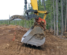
Figure 5-14 | Soil imprinting with modified excavator bucket
An alternative form of imprinting road cuts and fills that does not compact soils is welding angle iron onto the bucket of an excavator. As the excavator pulls top- soil into place and contours the slope, it presses the face of the bucket into the soil surface to form surface imprints.
Photo credit: David Steinfeld
An alternative to trackwalking is the use of the bucket of an excavator to pack and imprint the soil surface. Different patterns of steel “teeth” can be welded on the face of the bucket to achieve the desired surface micro-relief. Figure 5-14 shows an excavator bucket, with four strips of angle iron welded to its face, to create a pattern of 3-inch-deep impressions. The excavator, in this example, moves topsoil to the site, shapes the cut and fill slopes, and imprints the surface, all with one operation.
5.2.3 MULCHES
Introduction
Mulch is defined as a protective material placed on the soil surface to prevent evaporation, moderate surface temperatures, prevent weed establishment, enrich the soil, and reduce erosion. Mulches, therefore, have many functions or roles in the recovery of native vegetation to a disturbed site. Confusion often arises around the use of mulches on revegetation projects unless the reasons for using them are clearly defined. In this discussion, mulches are grouped into four uses based on the revegetation objectives:
- Seed Covering
- Seedling Mulch
- Soil Improvement
- Seed Supply
For most projects, mulches are used to meet more than one objective but this is problematic when the methods for achieving more than one objectives are not compatible. For example, erosion-control products and practices that are effective for controlling surface erosion are not always optimal for establishing vegetation. For this reason, it is important to understand the objectives for mulching when selecting mulch types and application methods.
This section describes the objectives for applying mulches and the potential mulch sources. Many publications and much research are available on the effectiveness of mulches for erosion control and surface stabilization. This discussion focuses primarily on the characteristics of mulches for plant establishment.
Seed Covering
One of the principal reasons for applying mulch is to enhance seed germination and early seedling establishment. During this critical period, desirable mulches will:
- Protect seeds and young seedlings from soil splash, sheet erosion, and freeze-thaw
- Keep seeds moist during germination
- Keep soils moist during seedling establishment
- Moderate surface temperatures during germination
- Prevent salts from wicking to the surface and harming germinating seedlings
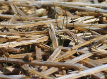
Figure 5-15 | Long-fibered mulches
Long-fibered mulches, such as the wood strands shown below, create a good growing environment because seeds and seedlings are protected from excessive drying during germination and early seedling establishment. On sites where freeze-thaw is prevalent, long-fibered mulches can insulate the soil and protect emerging seedlings.
Photo credit: David Steinfeld
The characteristics of mulch materials that make an ideal seed covering are those that protect seeds from drying winds, solar radiation, high evapotranspiration rates, and surface erosion while still allowing seeds to germinate and grow through the mulch into healthy seedlings. Long-fibered mulches placed at the appropriate thickness, usually meet these characteristics. A long-fibered mulch is composed of particles that are long and thin (at least several inches long with a length to width ratios of greater than 4:1). Such materials include straw, wood strands, pine needles, and shredded wood (ground or chipped woody material).
When applied correctly, the strands of long-fibered mulch loosely pack over each other, much like “pick- up-sticks,” forming large air spaces or pores (Figure 5-15). Large pores function much like the air spaces in building insulation by moderating extreme temperatures. The bridging effect of the long particles also makes some of these materials more stable, and less prone to erosion or movement. Depending on the long-fibered material and erosivity of the site, it may not be necessary to apply a tackifier, though heavier materials, such as shredded woods or wood strands are less susceptible to wind displacement than lighter material like straw.
Long-fibered materials that are not recommended for mulch unless they are stabilized include shavings and materials less than two inches in length (Robichaud 2013).
Short-fibered mulches are much shorter in length and are typical of materials found in hydromulches. Comparing short-fibered mulches to long-fibered mulches, long-fibered mulches can be applied at greater thicknesses, which help maintain surface soil moisture and higher humidity around germinating seeds and emerging seedlings. In addition, long-fibered mulches can mitigate the effects of frost heaving at the soil surface (Kay 1978), significantly reduce high surface temperatures (Slick and Curtis 1985), and allow sunlight penetration, which enhances seed germination and seedling establishment. Large pores created by long-fibered mulches also allow better gas exchange between the soil and atmosphere (Borland 1990).
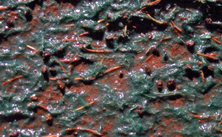
Figure 5-16 | Hydromulch
Hydromulch with tackifier can stabilize the soil surface for up to a year but does not necessarily create an optimum environment for germinating seeds. The short-fibered textures typically form a covering that is too thin to maintain moisture around the seeds during germination when the weather is dry. The hydromulch (dyed with a green tracer) shown in this picture is applied at approximately 1,500 lb/ac. This low application rate may be acceptable on sites where soil erosion potential is low and surface soil moisture is high and seeds do not need to be covered for germination.
Photo credit: David Steinfeld
Short-fibered mulches usually have smaller pores and form denser seed covers. These materials are applied thinly (Figure 5-16); therefore, they offer less insulation than long- fibered mulches and have less value as a seed covering. Some researchers suggest that very fine textured mulches can increase surface evaporation by wicking moisture from the soil to the surface of the mulch (Slick and Curtis 1985; Borland 1990; Bainbridge et al 2001).
These types of mulches are derived from several sources: paper fiber, which provides little cover or slope protection and more typically, wood fiber, which offers longer duration cover and slope protection. Short-fibered mulches are effective as an erosion-control cover when applied with a tackifier, but many are considered inferior to long-fibered mulches for germination and early seedling establishment (Kill and Foote 1971; Meyer et al 1971; Kay 1974, 1978, 1983; Racey and Raitanen 1983; Dyer 1984; Wolf et al 1984; Norland 2000). Recently developed products, like bonded-fiber-matrix (BFM) and High Performance Growth Media, are also applied hydraulically, but their fibers are mechanically kinked so that when applied at recommended rates provide loft and pore space suitable for better seed germination while also providing a high level of slope protection (Figure 5-17).
Compost are being used with increasing frequency on projects as a seed mulch. Composts are different from long-fibered mulches in that the fibers are much shorter in length (typically less than an inch) and composted. Because they have less loft, compared to long-fibered mulches, they do not perform as well, and may dry out faster, which could reduce germination rates on drier sites. When composts are applied to a slope with pneumatic blower or a high-speed conveyor to depths ranging from 1 to 2 inches, it is called a compost blanket. Seeding involves applying the compost blanket, then seeding and covering the seed with a ¼” to ½” depth over the seed. Most pneumatic blowers can mix seed with the compost and apply it as a thin layer over the compost blanket as a final pass. This is the easiest method, but if this is done, then increasing the seeding rate may be a good practice because some seeds will be near or on the surface of the compost, lowering the germination rate of the seed mix.

Figure 5-17 | High performance growth media
At 4,000 pounds per acre, High Perfor-mance Growth Media provides a quarter of an inch of loft which creates a better environment for germination than hydromulch.
Photo credit: David Steinfeld
Applying seeds with a pneumatic mulch blower is done by placing seeds in a “seed metering bin” attached to most mulch-blowing equipment. This equipment meters seeds into the mulch as it is being applied. The rate at which the metering system delivers seeds is calibrated prior to mulching to obtain the desired seed density (refer to Section 5.4.1 for seed calibration methods).
The application of a tackifier is important because the medium-length fibers of compost do not provide enough weight and bridging between particles to provide protection from wind and water erosion. With tackifiers, composts can adhere to steep slopes in high rainfall areas. Compost blankets have a high moisture holding capacity and its dark color captures heat which aids germination. In addition, compost blankets provide nutrients to plants, which eliminates the need for fertilizer, and over time increases soil organic matter. Compost derived from yard debris is readily available in some areas where it is produced to eliminate organic matter from the waste stream.
Erosion mats are another type of seed cover (Section 5.2.3, see Erosion Mats). These materials come in rolls or sheets, which are laid out on disturbed soils and anchored in place after seeds have been sown. They are composed of such materials as polypropylene, straw, coconut, hay, wood excelsior, and jute. Good characteristics of erosion mats for seed germination and early seedling growth are those with enough loft, or porosity, to provide for optimum seed germination.
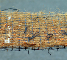
Figure 5-18 | Erosion mat
Erosion mats can be good seed covers. Mats with the highest loft create the best microenvironment for seed ger-mination while allowing some sunlight to penetrate to the surface of the soil. A consideration of the use of these products is how fast they decompose and the effects on wildlife.
Photo credit: David Steinfeld
Erosion mats create a micro-environment for seed germination while protecting the soil and allowing some sunlight to penetrate to the surface of the soil (Figure 5-18). It is important to recognize that the plastic netting in these mats degrade at varying rates depending on the climate and soil conditions. For example, on cool-dry sites, typical of high elevations, decomposition rates are slow and plastic may last for many years. Plastic netting that does not break down quickly can be a hazard to wildlife, entangling amphibians, reptiles, and birds. To reduce this hazard, many state DOTs are requiring that all erosion control mattings be fully biodegradable.
On sites where vegetation is expected to take several years to establish (e.g., arid, high elevation sites), it is important to apply a mulch with a longevity of more than one year. Materials with greatest longevity are most long-fibered wood mulches, as well as erosion mats made from coconut fiber. Straw, hay, and short-fibered products are less likely to be present after the first year however a High Performance Growth Media is available that is made of coconut fiber and it claims a 24-month functional life.
Mulching for seed covering is critical on sites that have high evapotranspiration rates during germination, unstable soil surfaces, susceptibility to freeze-thaw, or high soil pH. Mulching may be less important on sites where soil surfaces do not dry out during seed germination or on projects where seeds have been covered by soil.
Seedling Mulch
Mulch is placed around newly planted or established plants to improve survival and growing conditions by:
- Reducing surface evaporation
- Preventing the establishment of competing vegetation
- Moderating surface temperatures
- Allowing water infiltration
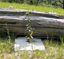
Figure 5-19 | Sheet mulch
Sheet mulches come in a variety of materials, such as the paper/cardboard product shown in this picture. The size of the sheet mulch is large enough to keep competing vegetation away from the seedling. The 3-by-3-foot sheet mulch shown around this Pacific madrone (Arbutus menziesii) seedling is the minimum size for this site.
Photo credit: David Steinfeld
Studies have shown that survival and growth of young trees are significantly increased by applying mulches around seedlings at the time of planting (DeByle 1969; Lowenstein and Pitkin 1970; Davies 1988a, 1988b). Mulching around seedlings results in the greatest benefit on hot and dry sites (typically south and west aspects) and sites with aggressive competing vegetation. It is less important to apply mulch around seedlings on sites that have a low potential for establishing competing vegetation the first several years after planting or sites that have low evapotranspiration rates or high rainfall during the summer months.
Seedling mulches are applied either as an organic aggregate, rock, or as sheet mulches. Organic aggregate mulches consist of shredded or chipped wood derived from bark, wood, branches, sawdust, or lawn clippings. Rock aggregate mulches consist of a layer of rocks placed around each seedling. Sheet mulches are large pieces of non- permeable or slightly permeable materials made from translucent plastic, newspaper, coconut fiber, or geotextiles (woven fabrics) that are anchored around planted seedlings (Figure 5-19).
Sheet Mulches—A variety of sheet mulches are available commercially. These mulches are popular because of the relative ease of transport and installation. The effectiveness of sheet mulches increases with the size of the sheets. For most hot, dry sites, a 2.5-by-2.5-foot sheet is considered the minimum dimension (Cleary et al 1988). On harsher sites, 3-by-3-foot or even 4-by-4-foot sheets are necessary to control competing vegetation. When purchasing and installing sheet mulches, it is important to consider (after Davies 1988a, 1988b):
- Selecting the right size—The size of the mulch is based on site conditions and the type and amount of competing vegetation. For example, a hot, south-facing site with full cover of competing grasses will need a large sheet mulch; a north-facing slope with scattered forbs and grasses will suffice with a smaller size.
- Ordering only opaque materials—Translucent materials are not used as sheet mulches because weed seeds can germinate and grow under these materials. During summer, surface temperatures under translucent materials can be lethal to seedling roots.
- Using sheet mulches with long life spans—It often takes three to five years for seedlings to become established on hot, dry sites and for this reason it is recommended that the sheet mulch have a durability of three years (Cleary et al 1988). The use of fully biodegradable materials is recommended.
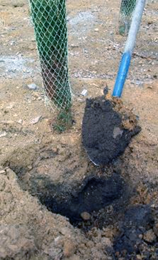
Figure 5-20 | Mulch conserves soil moisture and inhibits the establishment of unwanted vegetation
This photograph was taken in late summer, months after adjacent soils had dried out. The lack of competing vegetation and the low surface evaporation resulting from the placement of 3 to 4 inches of coarse sawdust resulted in very high soil moisture. In addition, the high C:N ratio of the sawdust was believed to be a factor in inhibiting the establishment of unwanted vegetation.
Photo credit: David Steinfeld
- Weeding or scalp around seedlings prior to installation—Sheet mulch cannot be installed properly without vegetation being completely removed.
- Mulching immediately after planting—In Mediterranean climates, waiting until later in the spring to mulch runs the risk that competing vegetation will have depleted soil moisture, thereby making the mulch ineffective during the first growing season. This can be avoided, by applying mulch during or immediately after seedlings are planted.
- Staking or anchoring all corners of the mulch—The sides of the mulch sheets can be easily detached by wind, animals, or competing vegetation growing under the mulch sheets. It is important that the corners are staked. Burying all edges of the sheets with soil provides the greatest effectiveness.
- Visibility—Sheet mulches can be very apparent in high visibility areas. Measures to reduce unsightliness of sheet mulches include covering with aggregate mulches such as hay, straw, or wood mulch, or selecting sheet colors that blend into the area.
Organic Aggregate Mulch—Organic aggregates are another group of materials that, when placed thickly around installed plants, will control the establishment of competing vegetation and reduce surface evaporation (Figure 5-20). These aggregates include hay, straw, or chipped and shredded wood materials. Organic aggregates are often used in highly visible areas because they are more aesthetic in appearance than sheet mulches. They are also used in planting islands for long-term control of competing vegetation.
The longevity of organic aggregate mulches is a function of the C:N ratio, texture, and depth. High C:N materials, such as uncomposted shredded wood, bark, or sawdust, will last longer than low C:N materials, such as composted yard materials, because these materials are in the initial stages of the decomposition cycle. Coarse-textured materials (Figure 5-21 A, B, C E, F), which include long-fibered mulches have greater longevity than finer-textured materials (Figure 5-21D) because coarser materials have less surface area per volume of material for microbial break down (Slick and Curtis 1985). Coarse-textured materials also tend to hold less moisture, which slows decomposition rates. The longevity of an organic aggregate mulch also depends on the application thickness—the thicker the layer of mulch, the longer it will last. In many climates, coarse-textured materials, such as shredded wood, can last for years on the surface of the soil.
The same factors that affect longevity (e.g., texture, C:N ratio, depth) also determine the effectiveness of aggregate mulches in deterring seed germination of unwanted vegetation around the seedling. Coarse-textured mulches are excellent because they hold very little moisture at the mulch surface and, therefore, are poor environments for seed germination of unwanted vegetation. Alternatively, fine-textured mulches create a more favorable environment for seed germination because they hold more moisture and are in closer contact with seeds. For this reason, many fine-textured materials, such as composts, are excellent growing media for weed seed germination and establishment. As discussed in Section 3.11.4, mulch materials with high C:N ratios discourage growth of weedy annuals because high C:N materials remove available nitrogen that would otherwise give these species a competitive advantage. The effectiveness of a mulch in discouraging the establishment of competing vegetation generally increases with the thickness with which it is placed on the soil surface (Baskin andBaskin 1989). The most effective mulch thicknesses are between 3 and 4 inches (Pellett and Heleba 1995; Ozores-Hampton 1998), but thicknesses as low as 1.5 inches are effective for some small-seeded weed species that need sunlight for germination (Penny and Neal 2003).
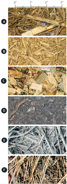
Figure 5-21 | Different types and textures of organic aggregate mulches
(A) freshly ground coarse shredded wood passing a 3-inch screen; (B) freshly ground coarse shredded wood passing a 1.5-inch screen; (C) freshly chipped wood; (D) composted mixtures of ground wood, biosolids, and yard wastes passing a 1.5-inch screen; (E) weathered straw; (F) ponderosa pine needles. All materials are coarse textured except compost (D).
Photo credit: David Steinfeld
Organic aggregate mulches have several advantages over sheet mulches. First, organic mulches can be applied over a much larger area than sheet mulches. Some projects have organic mulches covering the entire site, while other projects concentrate it in strategic areas, such as planting islands. Second, organic aggregate mulches moderate surface soil temperatures, whereas sheet mulches can increase surface temperatures. Mulch thicknesses of 3 inches have been found to reduce soil temperatures below mulch layers by 8 to 10 degrees F (Slick and Curtis 1985; Steinfeld 2004), which can benefit the growth of seedlings on very hot sites. The insulative quality of mulches also affects the seasonal heating and cooling patterns in the soil. Soils under thick mulches take longer to warm in the spring, but in the fall, take longer to cool down. Depending on the temperature and rainfall patterns of a site, this could influence seedling establishment.
Mulch can create problems to planted seedlings if it is placed in contact with the plant stem. The high moisture around the stem can be conducive to pathogenic injury. On southern exposures, heat will build up at the surface of, and directly above, the mulch, creating extremely high temperatures on warm summer days. The high temperatures can cause heat damage to stems of young seedlings. It is important, therefore, to keep mulch several inches away from the stem of planted seedlings.
Rock Mulch—Rock can be an effective mulch cover around seedlings. It consists of placing any size rock fraction (e.g. gravels, cobbles, stones) around each seedling. Rock protects the surface from erosion, evaporation, and weed establishment and it may be naturally available on a project site. As with organic aggregate mulches, rock is placed in a 1 to 2 feet radius around and at least several inches deep. Rock is kept away from the stem of the seedling to avoid heat damage. Prior to installation, unwanted vegetation is removed. One of the disadvantages of using rock mulch is that rock fragments can move downslope on steeper slope gradients and bury seedlings. Applying rock on gentler slopes or creating small planting benches where mulch can be placed around the seedling are recommended options.
Soil Improvement
Mulches are sometimes used specifically to increase the nutrient and organic matter status of a soil. Composted organic materials are used for these purposes and are characterized by having low C:N ratios, high nutrient levels, fine textures, and dark colors. While these materials are typically more effective when incorporated into the soil, they are sometimes applied to the surface of the soil where tillage is not feasible (steep and rocky) or tillage costs are unaffordable. Where composted organic materials are applied on the soil surface, the nutrient release rates will be much slower. Refer to Section 5.2.5 for more information on composts.
Seed Supply
The objectives for applying mulch on some projects are to spread materials that contain native seeds. Several mulch materials carry native seeds, including duff, litter, and straw from native seed production fields. When these materials are applied to the soil surface, seeds will germinate given favorable environmental conditions.
Litter and duff are organic layers that form on the surface of the soil under tree and shrub plant communities. They are years of accumulated leaves and needles at varying degrees of decomposition. Included in these layers are dormant seeds, many of which are still viable. When the duff and litter are collected and spread on disturbed sites, the environmental conditions for breaking the dormancy of the seeds present in the material may be met and seeds will germinate.
Litter and duff can be collected from adjacent forest- or shrub-dominated sites or salvaged prior to slope construction. Reapplying them to disturbed sites completes several operations at once: supplies native seeds, covers seeds, and increases long-term nutrient capital. Although this practice might seem expensive or impractical, when compared with purchasing and applying seeds, fertilizer, and mulch separately, the costs could be comparable. Refer to Section 5.2.3 (see Litter and Duff) for more information on litter and duff.
One of the byproducts of native grass seed production is the stubble that remains in the fields after seed harvest. This stubble contains varying quantities of unharvested seeds which eventually end up in bales. If bales are stored in dry conditions, seeds can remain viable for several years. When hay bales that contain the native seeds are spread as a mulch on disturbed sites, seeds come into contact with soil and eventually germinate. It is important when acquiring native hay that the species and the source of the seed lot is appropriate for the site. Refer to Section 5.2.3 (see Straw and Hay) for more information on straw and hay.
Selecting the Appropriate Mulch Materials
A variety of materials can be used as mulches, including the following:
- Shredded wood
- Erosion mats
- Hay and straw
- Manufactured wood strands
- Duff and Litter
- Composts
- Hydromulch
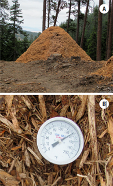
Figure 5-22 | Shredded wood piles are kept below 12 feet for safety reasons
Shredded wood piles generate heat as they compost (A). A 4-foot-long thermometer (B) can be used to determine internal pile temperatures. Some operations require piles to be turned when a specific temperature is reached.
Photo credit: David Steinfeld
The following sections describe these materials and how they are used in revegetation projects. Figure 5-21 shows examples of some of these mulches.
Shredded Wood
Mulches produced from woody materials are used primarily for seed covering and seedling mulching. There is usually a readily available source of wood material from project sites situated in forested environments. Branches, stems, bark, and root wads are typical waste products from clearing and grubbing that can be shredded, chipped or mulched on site to produce various types of wood mulch. In the past, this material has been burned or hauled to waste areas for disposal. With greater burning restrictions and higher hauling costs, chipping these materials and returning them to disturbed sites as mulch are practices that are becoming more common.
Shredded Wood Production—Creating mulch from right-of-way clearing woody material involves planning and coordination. First the road contractor piles the woody right-of-way clearing debris into “slash piles.” These piles include tree boles, bark, branches, and stumps, but it cannot contain large rocks or other inert materials that can cause wear or damage to the equipment. When clearing and piling is completed, a company that specializes in processing wood waste is contracted (typically by the road contractor). In this operation, equipment is brought to each slash pile and materials in these piles are processed into mulch. The resulting wood mulch is either placed in piles adjacent to the slash piles or transported to designated storage sites (Figure 5-22). The timing of these operations may be limited by fire restrictions in the western United States from mid-summer through early fall.
If undesirable plant species are included in the slash piles, spread of these species is likely to occur when they are processed and applied as a mulch. This can be prevented by identifying these plant populations on site during the weed assessment (Section 3.11.6) and avoiding placing them into slash piles.
It is important to define the desired mulch characteristics prior to processing the piles. For example, the size and shape of the wood particles will determine their stability and propensity to move down slopes. Long strains of wood particles tend to be more stable than short strains because they knit together and have greater weight. Obtaining the proper size and dimension can be difficult because there is a variety of wood waste reduction equipment that produce different dimensions and fibrosity (the degree that wood fibers are separated). Obtaining the desired particle size and shape by specifying a screen size the material should pass does not always produce the desired material.
Table 5-7 | General types of wood waste reduction equipment
Modified from Re-Sourcing Associates and CPM Consultants 1997
| General equipment types |
Examples |
Feedstock |
Particle geometry |
| Chippers |
Disc chippers, drum chippers |
Whole logs, clean residuals |
Clean edge, two-sided |
| Hogs |
Swing hammer, fixed hammer, punch and die, mass rotor |
Wood waste, stumps, land clearing debris |
Coarse, multi-surfaced, fibrous |
| Shredders |
Low speed-high torque, high speed |
Wood waste, stumps, land clearing debris |
Coarse, multi-surfaced, fibrous |
| Hybrids |
Knife hogs, pan and disc |
Wood waste, stumps, land clearing debris |
Semi-coarse |
Screens only sort for two dimensions, and not for length or fibrousness. Identifying the type of waste reduction equipment can narrow the type of mulch produced (Table 5-7). For example, mulch produced by shredders is long and fibrous (Figure 5-23 A and B), whereas mulch produced from chippers has sides that are of nearly equal lengths, with fibers still intact (Figure 5-23C). It is important that the correct equipment and screen sizes are used. It can be beneficial for the designer to request the contractor processing the material to send a sample of the different mulches that their equipment produces. In addition, being present at the beginning of the operations can assure that the proper material is being produced.
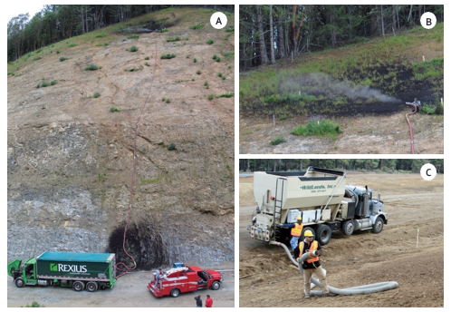
Figure 5-23 | Blowing equipment is used to apply mulch on steep slopes
Compost and shredded wood are applied on steeper slopes with mulch blowing equipment which is pneumatically delivered to the site through an application hose that can reach several hundred feet up steep slopes (A) with enough force for ample delivery of mulch (Image B is a close up of the application of mulch near the top of Image A). Large trucks can hold between 75 and 100 yards of mulch (A), while smaller trucks can hold up to 25 yards (C). A tackifier is added to compost to increase surface stability on steep slopes.
Photo credit: David Steinfeld
Generally, the coarser the size of the mulch, the less expensive the production costs because more mulch of coarser size can be produced in a given time frame than smaller textured mulch. Other factors, such as tree species, moisture content, and portion of tree processed, affect the characteristics of the mulch. If the wood is wet during processing, it is more likely to be shredded; if it is dry, it will be more chip-like. There is also variation in mulches based on species of origin. For example, ponderosa pine (Pinus ponderosa) and western juniper (Juniperus occidentalis) tend to create more fibrous mulch than lodgepole pine (Pinus contorta). Processed root wads tend to be more fibrous than boles of trees. They may also contain large rocks which will damage processing equipment and need to be removed prior to processing or set aside and not used.
The shredded wood operation needs space to store the pre-processed woody debris, operate the processing equipment, and a storage site for the processed shredded wood. Depending on the operation, this could require a significant area. It is important to consider the size of the processed shredded wood piles when determining space requirements. Standards for pile heights of no greater than 12 feet are often used for fire and safety reasons. Piles larger than this height may be prone to spontaneous combustion. Long stemmed thermometers are available to monitor interior pile temperatures. One consideration for pile locations is the distance to the areas being mulched. Travel time between mulch piles and application areas can be as longer than the actual application of the material.
Purchasing Shredded Wood—On projects where waste materials are not available for mulching, purchasing shredded wood may be an option. Overall costs are much higher than processing waste wood on site because of the purchase of the material and transporting to the site. If commercial mulch sources are nearby, transportation costs are significantly reduced. Testing the shredded wood is important to obtain suitable material. Methods and specifications can be developed that are similar to those provided in Section 5.2.5, or available in the Native Revegetation Resource Library.
Applying Shredded Wood—Shredded wood is applied in several ways—pneumatic mulch-blowing equipment, adapted manure spreaders, and rock slingers. Pneumatic mulch blowing equipment (Section 5.2.3, see Seed Covering) has varying transport capacities, ranging from 25 to 100 yards of material (Figure 5-23).
An application hose is positioned where mulch is to be applied and is pneumatically delivered from the mulch bins to the site. The amount of mulch applied depends on the revegetation objective. For seeding, application rates range from 100 yd3/ac (0.75-inch thickness) to 135 yd3/ac (1.0-inch thickness). For seedlings, mulch application ranges from 400 yd3/ac (3-inch thickness) to 540 yd3/ac (4-inch thickness). Note: The higher rates used for mulching seedlings are only used in close proximity to the plants. The remaining areas are mulched at a lower rate.
When applying shredded wood for erosion control objectives, the particle size of the material may be as important as the amount of material applied. On compacted soils, where overland flow is expected from heavy rainstorms, shredded wood lacking material smaller than an inch thick in length performs better in reducing sediment loss than material with finer wood. This coarse material can be applied at 50 to 60 percent ground coverage with good erosion control (Foltz and Wagenbrenner 2010).
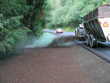
Figure 5-24 | A manure spreader adapted to side cast shredded wood
Shredded wood can also be casted from adapted manure spreaders. On this project, the seed mix was sown using a hydroseeder, then 0.75 inches of shredded wood was applied over the seeds.
Photo credit: David Steinfeld
Application rates depend on factors such as length and diameter of hose, blowing equipment, elevation rise, and dimensions of the area being covered. Rates of application typically range from 25 to 35 yd3/hr. If mulch is applied at a 1-inch depth (134 yd3/ac), it would take between 4 to 5 hours to cover an acre. These are optimum rates because they do not account for the time it takes to travel to the mulch source, load the mulch bin, and travel back to the application site. The time required to make these trips can sometimes be longer than the actual application time for mulching. Using larger transport capacities is one way to significantly reduce the time associated with refilling mulch bins.
Mulch blowing equipment can be used on any slope gradient that can be accessed by foot. By using ropes, slope gradients of up to 1H:1V can be accessed. Hose lengths can be attached to extend the delivery of mulch up to 400 feet. Because mulch is delivered through hoses, the system will plug if the size of the shredded wood exceeds the tube size. It is therefore important that mulch be free of large pieces of wood. Using a mulch blower is an excellent method for evenly applying shredded wood, but frequent monitoring by inspectors is important to ensure that the specified amount of mulch is being applied.
Shredded wood can also be applied with modified manure spreaders (Figure 5-24). Depending on the type of modifications, this equipment can apply shredded wood at a much faster rate than mulch blowing equipment, however this equipment generally is limited by the distance it can cast the material which is typically ranges from 35 to 75 feet depending if it is being applied upslope (less distance) or downslope (greater distances). Tackifiers are not typically applied to shredded wood after it is placed because this material is less susceptible to wind erosion than mulches that are finer textured and lighter.
Seed Placement during Mulching—Seeds can be sown prior to or during mulch operation. Seeds that are sown prior to mulching can be done with dryland sowing methods, hydroseeding, or through the pneumatic mulching equipment (Section 5.2.3, see Seed Covering). A thicker layer of shredded wood is applied in a second pass at a depth between 0.5 and 1.0 inches over the seed.
Erosion Mats
Erosion mats (e.g. erosion control revegetation mats and rolled erosion control products) are manufactured blankets or mats designed to increase surface stability and control erosion. They are applied in direct contact to the soil surface for control of sheet erosion and to aid in the establishment of vegetation.
A multitude of products are on the market, with a range in design and costs. Determining which products will meet project objectives at the right price can be challenging. Several State Departments of Transportation periodically evaluate and compare the shear stress, soil erosion protection, longevity, and other characteristics for these products (Caltrans 2003), and these documents are available on the internet. State of Washington and State of Oregon DOTs are moving to require that all erosion control mattings be fully biodegradable. Because the installed costs of erosion mats can be expensive, it is important that the job is done correctly. Taking the time to select the appropriate erosion mats, native species mix, and seed placement techniques is essential for ensuring that revegetation is successful. Small field trials using different species and erosion mats can help in these decisions (Figure 5-25).
The same characteristics that create an optimum environment for seed germination in other mulches are also important to consider when selecting erosion mats. Typically, products that protect the seeds from drying out but allow light and space for germinating seedstogrow into seedlings will perform best for vegetation establishment. The thicker erosion mats with the most loft typically have better conditions for seedling establishment than thinner materials how- ever, if the mat is too thick, seedlings will not be able to emerge from the fabric.
The drawbacks to erosion mats are generally not in the product itself but in how it is applied to the site. Poorly applied erosion mats can result in sheet and rill erosion under the fabric. To avoid this problem, several important measures can be taken when installing erosion mats. First the surface of the soil is smoothed to a uniform fabric to prevent overland water flow from undercutting the mats.
Seeds are sown on the site prior to installing erosion mats. Because installation is commonly performed by the road building contractor, it is important that the designer works with the contractor to assure that seeds are being sown during the surface texture before the mat is placed. Landscape staples or pins are then installed at a specified spacing to hold the matting and ensure in intimate contact with the soil surface. The matting is trenched or keyed into the soil at the upper reaches of the seeding windows. Seeding can be done using any type of seeding method (e.g., hydroseed, slopes have been sown, care taken during and after mat installation can help avoid disturbing the seed. Unless the seeds are extremely small, sowing seeds over installed erosion mats is not recommended because larger seeds will hang up in the fabric. Small seeds can be applied over erosion mats if tackifiers are not used and if the timing is such that sufficient rain will move it through the erosion mat to the soil surface.
Some manufacturers offer erosion mats that are impregnated with seeds, eliminating the need for sowing. This method is advantageous on steep slopes or soil-faced gabion walls (Inset 5-3) where placing seed prior to mat installation is difficult. It is important to work directly with companies that provide these products by supplying them with source-specific seeds and specifying appropriate sowing rates. For successful germination, seeded erosion mats are installed so that seeds and fabric are in direct contact with the soil. This method works best in environments with reliable moisture during germination.
Inset 5-3 | Case Study—Erosion mats with native grasses and forbs
Reconstruction of the Agness-Illahe Highway involved building long sections of gabion walls. Because this highway was visible from the Rogue River (a designated “wild and scenic” river in southwestern Oregon) and was heavily traveled by river runners and fishermen, it was important that the gabion walls be visually screened using native plants. Gabions were designed to hold 12 inches of compost-amended soil (topsoil was not available) on the face of the walls by wire mesh frames (Image A in the illustration below). Placement of seeds at the surface of the gabion wall was problematic. Several small plots using different erosion mats, seed mixes, seed rates, and seed-attaching methods were tested to determine how to best meet the revegetation objectives (Figure 5-25).
The results from these trials indicated that native grass and forb seeds could be attached to erosion mats using a tackifier (Image B). In 2003, the findings were applied to the construction project. Needing approximately 33,000 ft2 of gabion wall facing, the erosion mats were prepared by rolling them out on a road surface, applying California fescue (Festuca californica), gluing the seeds to the mat, and re-rolling the erosion mats.
The seeds held tightly to the fabric during transportation and handling. At the construction site, seeded mats were attached to the wire mesh at the face of the wall (Image C) and compost-amended soil was placed behind the screen and lightly tamped. The gabion walls were built in the summer of 2003, but the seeds did not germinate until late fall after several rainstorms. Image D shows a close-up section of wall with newly germinating seedlings emerging through the erosion mat in late 2003, four months after wall construction. Image E shows 20- to 30-foot-high walls in July 2006, three years later, fully vegetated and effectively screening the walls from the road and river). For more detail, see the Native Revegetation Resource Library.
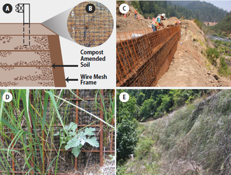
Straw and Hay
Straw and hay are long-fibered mulches used on many revegetation projects for seed cover and erosion control (Image E in the illustration in Inset 5-3). The terms “straw” and “hay” are often used interchangeably, however there are distinct differences—straw is the stubble left over after seeds have been harvested from commercial seed or grain crops while hay comes from grass/legume fields and usually the whole plant baled for stock feed. When hay is harvested, it usually contains seeds from a variety of pasture species.
Straw and hay are often used on revegetation projects because they are available, comparatively inexpensive, and generally successful in establishing grass and forb plants from seeds. The long stems of these materials create loft, or high porosity, that keeps moisture near the soil surface where seeds are germinating. This creates a favorable environment for young seedlings by allowing sunlight to penetrate and protecting the young seedlings during the early stages of establishment.
Inset 5-4 | Source identified straw bales
A secondary product from the seed production contracts is the straw that remains after harvest. This material can be used for erosion control or seed covering. It can be used as a mulch and has the additional advantage of being a source of unharvested viable seed. This product is to be treated similarly to certify straw sources (Section 5.2.3 (see Straw and Hay). No noxious or undesirable weed seed should be in the bales. A visit to the seed production fields prior to seed harvest will indicate if there are any unwanted species that will be present in the hay bales. Good practice is to keep bales of each seedlot separate from other sources to prevent mixing. If straw bales are stored for any length of time, good practice is to protect them from rain.
Straw is often preferred over hay because it generally contains fewer undesirable seeds and the seeds that are contained in straw are not always inappropriate for use in revegetation projects. For example, straw from some grain production fields (e.g., rice straw) has seeds of species that are not adapted to many environments and therefore may not become established. Straw produced from native seed production fields may have desirable seeds if the fields are grown from identified genetic sources and used for projects within the appropriate seed transfer zones (Inset 5-4). Using source-identified straw not only act as a mulch when it is applied, but it also supplies extra native seeds to the site. Some native grass species grown for seed production are very difficult to harvest and clean. One strategy for these species is to allow the seeds to ripen in the fields and bale the seeds and stems together. The seeded bales can be applied directly to the site through straw blowing equipment, accomplishing seeding and mulching in one operation.
Purchasing Straw and Hay—The drawbacks to using straw and hay are that these materials can contain seeds from undesirable species, are susceptible to wind movement, may have limited application distance, and decompose in a relatively short time compared to other mulches. Introducing seeds of undesirable species from straw and hay sources is an important consideration when choosing a source. There are many examples where, in the urgency of erosion control, straw or hay from unknown sources has been applied, resulting in the introduction of weed species. The assumption is that short-term control of soil erosion and sediment production outweighs the long-term introduction of undesirable plant species. The possible results from these assumptions need to be understood and agreed upon prior to applying hay or straw from unknown sources. Good integration of erosion control and revegetation planning can eliminate the need for last-minute purchase and application of unknown or undesirable hay or straw sources.
Many states have certification programs that inspect fields and certify that the bales are “weed free” which means that the material is free of the noxious or listed weeds of the inspecting state. There can be other seeds in the bales, however, that may not be considered weeds by the certifying state, but unwanted on the project site. A conservative approach is to examine the fields that will produce the bales and observe which species are present before they are harvested. It can be assumed that if a species of grass or forb is present in a field, seeds from these plants will show up in the bales.
Some things to consider requiring when purchasing straw or hay are as follows:
- Does the source exceed State Certification Standards for “weed free”? Many states have straw certification programs but for states where no standard programs exist, acceptance can be based on seed crop inspection reports and/or visual field inspections prior to harvest. Standards may also be set by the Government and listed on individual task orders.
- Is straw or hay baled and secured? Generally, bales less than 100 pounds work best.
- Are bales wet after harvest or during storage prior to delivery? Not only is wet material harder to handle and less effective, mold is often present, which can pose respiratory risks to applicators.
The quality of straw and hay varies among grass species. Rice straw, for example, is wiry and does not readily shatter, which makes it more difficult to apply as compared to wheat, barley, or oats (Kay 1983; Jackson et al 1988). Native straw is generally longer and stronger than grain straw (Norland 2000), although some native species have better properties as mulches than others. Larger stemmed grasses, such as blue wildrye (Elymus glaucus), mountain brome (Bromus marginatus), andbluebunch wheatgrass (Pseudoroegneria spicata) make good mulches because of their large leaves and stems.
Application—Straw and hay can be spread by hand or with a straw blower. For large jobs, using a straw blower is the most practical application method. Many types of straw blowers are available, ranging from very small systems (Figure 5-26) that deliver from 30 to 180 bales per hour to large straw blowers that operate at rates up to 20 tons per hour. The distance that straw or hay can be blown depends on the hay-blowing equipment, wind conditions during application, straw characteristics, and whether the material is being applied upslope or downslope (cuts or fills). When wind is favorable, straw can be shot up to 100 feet. However, when wind is blowing against the direction mulch is being applied, the distance is reduced. Because of the limited application range, this equipment is limited to sites adjacent to roads. The upper portions of steep, extensive slopes are typically not reachable by straw blowers.
When straw is used as a seed mulch, it is important that the application rates are not so deep that a physical barrier is formed. A minimum depth that has been shown to control evaporation is 1 inch (Slick and Curtis 1985). Applying too much straw will restrict sunlight and growing space for establishing seedlings. A rule of thumb is that some surface soil (15 percent to 20 percent) is visible through the straw after application (Kay 1972, 1983; Jackson et al 1988). This equates to 1.5 to 2 tons per acre, depending on the type of straw and its moisture content. This rate can be adjusted based on the climate of the site.
Straw is susceptible to movement with moderate to high winds. Tackifiers are often applied over the straw to keep it in place (Kay 1978). Products such as guar and plantago are used with low quantities of hydromulch to bind straw together. Straw can also be crimped, rolled, or punched into the soil. A puncher is a roller with a set of straight studs, greater than 6 in long, that push straw into the soil. A crimper is similar but has serrated disks attached to a roller. This equipment stabilize the straw by burying portions of the stems into the soil and increase erosion protection because of the greater contact of straw with the soil surface. Some soil types may not be suitable for crimping, especially sandy soils that may not have the strength to hold straw in place. It is important to consider the potential for soil compaction that may result from heavy equipment on soils.
Wood Strands and Wood Wool
Wood strands and wood wool are commercially available wood products used for mulch. Wood strands are long, thin pieces of wood produced from wood waste veneer, whereas wood wool, known as excelsior, is wood slivers produced from aspen, spruce, and pine wood. These products are developed as an effective erosion-control alternative to straw and hay (Foltz and Dooley 2003). The advantages of wood strands and wood wool over straw are that they are free of seeds, have greater longevity, and more resistant to wind.
Wood strands and wood wool form a stable surface cover with high porosity or loft; characteristics that are important for controlling soil moisture and temperature around the germinating seeds. The large spaces or pores created by the wood strands allow space, light, and protection for young emerging seedlings (Figure 5-15). Unlike straw, these materials keep their structure or porosity over time and do not compress with snow or lose fiber strength until they begin to decompose. The application rates for wood strands follow the guides for straw—at least 15 percent to 20 percent of the soil surface is visible. This may result in a lower application rate than recommended for erosion control. Installing small test plots of varying thicknesses of mulch is a good means to determine the appropriate thickness for optimum seed germination and erosion control. Wood strands are delivered in different size bales and applied by hand or through straw-blowing equipment (Figure 5-26). As with straw, this product is limited by the accessibility of the site by hay transportation and blowing equipment.
Litter and Duff
Litter is the layer of fresh and partially decomposed needles and leaves that cover the surface of most forest and shrub plant community soils. Duff is the dark, decomposed layer directly below the litter layer (leaves and needles are not identifiable in the duff layer) that is high in nutrients and humus. In addition to providing soil protection and nutrients, litter and duff can contain dormant, yet viable, seeds from species that make up the forest or shrub plant communities (Section 5.2.3, see Seed Supply). When litter and duff are collected, matching them to the appropriate revegetation site is good practice. For example, litter and duff collected from cool, moist sites are not to be applied on hot, dry sites.
Inset 5-5 | Pine straw industry
Using forest litter as a mulch is not a new concept—pine needles have been a popular landscaping mulch in the southern United States for the past 25 years. The “pine straw” industry, as it is referred to, has been established to harvest needles in a sustainable manner from young plantations of southern pine species to meet this demand.
The depth that litter and duff accumulates will vary by species composition, age, and productivity of the plant community. The quality of the litter for erosion control and longevity varies by the dominant forest or shrub species. Pine needles provide the greatest benefit because the long needles interlock, reducing the potential of movement from rain or wind erosion (Inset 5-5) (Image F in Figure 5-21). Needles from species such as Douglas-fir are shorter and tend to compact, providing less surface stability. Litter from deciduous tree and shrub plant communities provide less protection because the leaves are less interlocking, provide less loft, and often form a mat that can be difficult for germinating seeds. Nevertheless, these materials can be a source of seeds and nutrients and not to be immediately overlooked.
In the western states, litter has typically been collected manually by raking. The collection of litter has been mechanized in the southern United States, and the pine straw industry is well developed in this part of the country. Baling equipment has been developed for this industry and could be applicable to the western United States. Collection of needles and duff is done when the litter and duff are dry. If these materials are not used immediately, they are placed in small piles and covered with plastic to keep the materials dry. Excessive moisture can turn the piles into compost and possibly affect seed viability.
Litter and duff can be applied manually to disturbed sites. If the litter and duff is free of large materials, it can be applied in a variety of ways including pneumatic mulch blowers, straw blowers, and modified manure spreaders.
One method for determining the amount of viable seeds in a litter layer is to conduct a germination test at the project site over a several-year period by obtaining litter and duff from several potential collection areas and testing them on nearby sites. Dry litter and duff samples are collected from each plant communities and a known amount is weighed. The samples can either be spread in an area near the project (free of vegetation and topsoil) or on potting soil in a garden or greenhouse. In either case, the duff and litter is overwintered and a germination count is made in the spring. The numbers of seedlings per known volume or weight of litter and duff material is used to determine the rate of litter to be applied.
5.2.4 TOPSOIL
Introduction
Topsoiling is the salvage, storage, and application of topsoil material to provide a suitable growing medium for plants and to enhance soil infiltration (Rauzi and Tresler 1978; Woodmansee et al 1978; Natural Resource Conservation Service (NRCS) 1994). Topsoiling has been found to increase plant cover and biomass through an increase in nutrient availability, water-holding capacity, and microbial activity, including mycorrhizae (Claassen and Zasoski 1994).
While topsoiling has many benefits for revegetation, topsoiling cannot re-create the original undisturbed soil. In the process of removing and reapplying topsoil, soils undergo a loss of soil aggregation, organic nitrogen, arbuscular mycorrhizal fungi (AMF) inoculum, and microbial biomass carbon (Visser et al 1984). Minimizing topsoil disturbance is preferred to topsoiling, especially on sensitive soils, such as those derived from granitic and serpentine bedrock (Claassen et al 1995).
Salvaging Topsoil
Salvaging topsoil is done in areas that will be severely disturbed during construction. These areas are usually identified early in the planning stages. Topsoil within these areas can be surveyed to determine the depth and quality of the topsoil that can be excavated. If weeds are observed during the field survey, it is a good possibility that the seeds of these species are present in the topsoil. These areas can be avoided or undesirable vegetation treated prior to topsoil removal. Ideally, only the topsoil, and not the subsoil, is removed in the excavation process. Mixing subsoil into the topsoil will dilute microbial biomass and mycorrhizal inoculum and reduce the quality of the topsoil.
During topsoil excavation, the litter and duff layers are removed together with the topsoil. These layers are sources of decomposed and partially decomposed organic matter which will undergo some decomposition, releasing nutrients and organic matter to the soil during storage. There are circumstances where the duff/litter layer is removed and stored separately from the topsoil which is when the duff and litter are to be used as a native seed source or soil cover (Section 5.2.3, see Seed Supply).
Topsoil layers are typically removed with either the blade of a tractor or excavator bucket. Where precision is important, using an excavator bucket is the preferred tool. Thin topsoils, common on high elevation sites or soils where the subsoil cannot be mixed with the topsoils (e.g. subsoils with very high or low pH, high sodium, high salinity) can be scraped with the front of the excavator bucket to the desired depth. There is less depth control when using a tractor.
Topsoil is typically moved into berms at the bottom of fill slopes or the top of cut slopes and stored there until it is reapplied or transported to a storage area. This will likely require that the storage areas along the cut and fill slopes will have minimal amount of disturbance until the soil is reapplied. Typical berm dimensions are approximately 6 feet wide by 3 feet high. In areas where there is more topsoil than can be stored on-site, topsoil is trucked offsite to larger storage piles. When selecting off site storage areas, it is important to assess the site and surrounding area for unwanted vegetation because of the potential that this vegetation will become established on the topsoil piles. It is also important to plan salvaging operations so that there is a minimal amount of compaction prior to removal. This will likely require keeping large equipment travel on salvaged topsoil areas to a minimum.
To maintain optimum soil quality, it is best to excavate topsoil when soils are relatively dry. Under dry conditions, there is less potential to compact the soil, destroy soil aggregation, or oxidize organic matter. Dry topsoil store longer and maintain better viability than moist topsoil (Visser, Fujikawa, et al 1984). Restricting topsoil excavation operations to dry periods for large topsoil piles, or if topsoil is to remain in piles for more than one year, will increase the viability of the topsoil.
Storing Topsoil
The question often raised around storing topsoil is how long it can remain piled before it loses its viability. Studies have shown that stored topsoil can remain viable from six months (Claassen and Zasoski 1994) to several years (Miller and May 1979; Visser, Fujikawa, et al 1984; Visser, Griffiths, et al 1984,) but will decrease in viability after five years (Miller and May 1979; Ross and Cairns 1981).
Viability of stored topsoil is a function of moisture, temperature, oxygen, nitrogen, and time. Stockpiled topsoil has been compared to “diffuse composting systems” (Visser, Fujikawa, et al 1984) because, under optimum conditions, organic material in the topsoil will compost. Decomposition of organic matter in stored topsoil will reduce microbial biomass essential for nitrogen cycling (Ross and Cairns 1981) and fine roots that store mycorrhizal inoculum (Miller and May 1979; Miller and Jastrow 1992). Optimum environments for decomposition include high moisture, warm temperatures, and available nutrients, all conditions present in most topsoil piles. Climates with lower moisture and temperatures can be more favorable to long-term storage. A study in Alberta, Canada, for example, revealed that topsoil had very little respiration or organic decomposition after three years in a stockpile due to the influence of the cold, dry climate (Visser, Fujikawa, et al 1984). Dry topsoils store longer and maintain greater populations of viable mycorrhizal fungi (Miller and Jastrow 1992). Topsoil piles that will be held over winter in areas of moderate to high rainfall will benefit by covering with plastic to keep the soil dry. This will also keep the piles protected from erosion and weed establishment.
The size of the pile can also affect the viability of the topsoil. The interior of large piles maintains higher temperatures and are usually anaerobic, which can be detrimental to soil microorganisms. Microbial biomass levels and mycorrhizal fungi have been found to be very low in the bottom of large stockpiles (Ross and Cairns 1981; Miller and Jastrow 1992). Most projects limit topsoil piles to 3 to 6 feet in height. This is not always possible, especially when topsoil storage space is limited. Under these circumstances, the size of the topsoil pile can be quite large. To reduce the negative effects associated with very large piles, topsoils can be salvaged dry and kept dry during storage. They can also be stored for as short a time as possible. In addition to maintaining the viability of the topsoil, minimizing storage time will reduce the risk of weed infestation.
Standard specifications often call for temporary seeding of topsoil piles. The benefits of this practice are erosion control and maintenance of mycorrhizae inoculum through the presence of live roots. This practice also runs the risk of introducing undesirable plant species that may be present in the seeding mix if a non-native species mix is used. Alternatives to this practice include hydromulching without seeds or covering with plastic however, both practices lose their effectiveness with time.
Reapplying Topsoil
The depth of topsoil application is generally based on the amount of topsoil available and the desired productivity of the site after application. As a rule, the deeper that topsoil is applied, the greater the site productivity. If the objective is to restore a site to its original productivity, consider placing topsoil at a depth equal to or greater than the topsoil horizon of undisturbed reference sites. Sufficient topsoil quantities, however, are rarely available in the quantities needed to restore disturbed sites to their original topsoil depths. This often leads to applying topsoil too thinly across a project site. There may be a minimum topsoil depth below which the application of topsoil is not effective. Research on a northern California road construction site (Claassen and Zasoski 1994) suggests that a depth of 4 to 8 inches is necessary for an effective use of topsoil. On sites where the subsoil is unfavorable for plant establishment (e.g., very high or low pH, high sodium, high salinity), minimum depths of greater than 12 inches of topsoil may be considered (Bradshaw et al 1982).
Determining minimum topsoil application depths can be based on the minimum amount of N required to establish a self-maintaining plant community. A threshold of approximately 700 kg/ha (625 lb/ac) of total nitrogen in the topsoil has been suggested for sustaining a self-maintaining plant community in a temperate climate (Bradshaw et al 1982). Claassen and Hogan (1998) suggest higher rates, especially on granitic soils, of 1,100 lb/ac total nitrogen. Using total nitrogen levels from soil tests of topsoil in reference areas, the application thickness of topsoil can be determined using the calculations presented in Figure 5-27.
Some sites, like high elevation and desert environments, have very little topsoil to begin with. In these areas, salvage and application of topsoil may be less than 4 inches depending on the topsoil depth of the reference site. While this may not seem worth the effort, the addition of a thin layer of salvaged topsoil may provide soil organisms and seeds that are essential for restoring the site to original productivity and species composition.
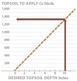
Figure 5-28 | Determining the soil quantity needed for a specific topsoil depth
The quantity of topsoil to apply to achieve a specified topsoil thickness can be estimated using this graph. For example, to create a topsoil, 10-inches deep, would require 1,350 yd3 of topsoil.
Once the desired topsoil depth has been established, then it can be determined if there is enough salvaged topsoil available. The quantity of topsoil needed can be determined based on the depth of topsoil from Figure 5-28. For example, if an average of 10 inches of topsoil is needed on a project, approximately 1,350 yd3/ac topsoil will be necessary. If there is not enough topsoil to meet this depth, then an alternative approach may need to be taken, including strategic placement of topsoils, or areas where topsoil depths are reduced. The strategy might concentrate topsoil in areas such as planting islands, planting pockets, or in a mosaic pattern that blends with the natural vegetative community. In areas that have reduced or no topsoil, other mitigating measures could be used, such as incorporation of organic matter into the subsoil or mulching.
Manufactured Topsoil
The term manufactured topsoil (also referred to as “engineered topsoil”) is used to define a soil created to perform like, or develop into, topsoil. It is usually manufactured offsite and transported to the area where it is applied. Manufactured topsoil is used in gabion walls, crib walls, or other bioengineered structures. It can also be used in planting pockets and planting islands.
Selection of the appropriate organic matter, soil texture, and soil amendments for manufactured topsoil will increase the success of the project. It is critical that manufactured topsoil be similar to the soils of the reference site with characteristics that will support the desired plant community. The basic components of a manufactured topsoil are the loam borrow, compost, and soil amendments.
Loam Borrow—Loam borrow is any material that is composed of mineral particles meeting a suitable texture class (Figure 5-29). Optimal loam borrow is low in coarse fragment content, is weed-free, and meets general soil quality specifications shown in Table 5-8. Testing loam borrow will determine if the material meets these general specifications. Loam borrow can come from many sources, such as subsoils, river sands, and terrace deposits. When loam borrow comes from subsoils or parent material, it can be assumed that beneficial soil micro- organisms, like mycorrhizae and nitrogen-fixing bacteria are not present. These microorganisms can be added to the loam borrow using inoculums (Section 5.2.7).
Compost—The organic component of manufactured topsoil (Section 5.2.5, Organic Matter Amendments) is composted materials from of a variety of materials, including yard waste materials (grass clippings, leaves, and shredded wood of trees and shrubs), sawdust, and biosolids. The heat generated during composting effectively reduces pathogens, weeds, and insects that may be hazardous to humans and detrimental to the reestablishment of vegetation. To reduce the potential for spreading weeds, compost specifications call for material that is free of weed seeds and vegetative material that may propagate weedy plants (e.g., blackberry canes). Specifications also call for well-composted, or stable, which can be indirectly determined by a respirometry test or calculated using C:N ratios obtained from laboratory testing of nitrogen and organic matter. A stable compost will have a low respirometry rate (<8 mg CO2-C per g organic matter per day) and low C:N (<25:1). A bioassay test that compares the rate of seedling emergence and seeds sown in compost to seeds sown in a control growing medium would be useful. Table 5-9 lists the laboratory tests for determining the optimum composts to use in manufactured topsoils.
Table 5-8 | General specification ranges for loam borrow used in manufactured topsoil
This table outlines the general specifications for loam borrow used in manufactured topsoil. It can be adapted depending on the soil characteristics of the compost and other soil amendments that will be used in the composition of the manufactured topsoil (modified after Alexander 2003b).
| Test parameters |
Test methods |
Loam borrow |
| Physical contaminates (man-made inerts) |
Man-made inert removal and classification (TMECC 0.308-C) |
<1% |
| Trace contaminants |
Arsenic, Cadmium, Copper, Mercury, Manganese, Molybdenum, Nickel, Lead (TMECC 04.06) |
Meets US EPA, 40 CFR 503 Regulations |
| pH |
1:5 slurry pH (TMECC 04.11-A) |
5.0-7.5 |
| Soluble salts |
Electrical conductivity using 1:5 slurry method (dS/m) |
<5 |
| Biossay |
Percent seedling emergence and relative seedling vigor (TMECC 05.05-A) |
>80% of control |
| C:N ratio |
(TMECC 05.02-A) |
<25 |
To ensure the delivery of high quality organic materials, compost can be obtained from a facility that participates in the Seal of Testing Assurance (STA) program (Inset 5-6). Upon request, these compost facilities send the latest lab results of the material of interest. If compost is from a STA composting facility is not available, other sources can be considered but testing the quality of the compost will be the responsibility of the designer. Compost testing by the designer involves sampling the compost piles and sending the samples to an STA lab (a listing can be found at the Composting Council’s website).
At the same time that compost piles are tested, they can also be visually inspected to ensure that noxious weeds are not present on or near the composting facility.
The compost application rates typically range from 10 to 30 percent by volume of the loam borrow. Section 5.2.5 describes how to determine specific organic matter rates.
Soil Amendments—Soil amendments, such as fertilizers, lime, and beneficial microorganisms, can be applied to the compost and loam borrow to bring the manufactured soil into acceptable ranges for pH, nutrients, and microbiological parameters. The type and amount of amendments to apply can be determined by conducting a lab analysis on a sample of the manufactured topsoil (e.g. the combination of loam borrow and compost at the specified mixing ratio). From the results of the soil analysis, a determination can be made for the application rates for fertilizers (Section 5.2.1), lime amendments (Section 5.2.6), and beneficial soil microorganisms (Section 5.2.7).
Table 5-9 | General specification ranges for composted materials for composted materials in manufactured topsoil
These generalized specifications for composts to use in manufactured topsoil can be adapted depending on the soil characteristics of the loam borrow and site conditions. Modified after Alexander 2003b
| Test parameters |
Test methods |
Loam borrow |
| Physical contaminates (man-made inerts) |
Man-made inert removal and classification (TMECC 0.308-C) |
<1% |
| Trace contaminants |
Arsenic, Cadmium, Copper, Mercury, Manganese, Molybdenum, Nickel, Lead (TMECC 04.06) |
Meets US EPA, 40 CFR 503 Regulations |
| pH |
1:5 slurry pH (TMECC 04.11-A) |
5.0-8.5 |
| Soluble salts |
Electrical conductivity using 1:5 slurry method (dS/m) |
<5 |
| Biossay |
Percent seedling emergence and relative seedling vigor (TMECC 05.05-A) |
>80% of control |
| % Moisture content |
Percent wet weight (TMECC 03.09-A) |
30-60 |
| Total organic matter |
Percent by dry weight, loss on ignition (TMECC 05.07-A) |
25 to 60% |
| Stability |
Respirometry. Carbon dioxide evolution rate — mg CO2-C per g OM per day (TMECC 05.088) |
<8 |
| C:N ratio |
(TMECC 05.02-A) |
<25 |
| Particle size |
Percent of compost by dry weight passing a selected mesh size, dry weight (TMECC 02.12- B) |
- 3” (75mm): 100%
- 1” (25MM): 90-100%
- 3/4” (19mm): 65-100%
- 1/4” (6.4mm): 0-75%
- Maximum particle length of 6” (152mm)
|
Large quantities of manufactured topsoil can be mixed in a staging area. Using the bucket of a front-end loader or excavator, the compost and loam borrow can be measured out proportionately. For example, using a 5 yd3 bucket, manufactured topsoil with a ratio of 25 percent compost and 75 percent loam borrow would have one scoop of compost applied to three scoops of loam borrow to produce 20 yd3 of material. Additional amendments, such as fertilizers or lime materials, would be applied based on calculations for a 20 yd3 pile. Once all the materials have been placed in the pile, it is thoroughly mixed using the front-end loader.
Purchasing loam borrow, compost, and topsoil will likely involve a set of contract specifications that ensure product quality. The specifications in Table 5-8 and Table 5-9 were developed for the U.S. Department of Transportation by the Composting Council Research and Education Foundation (Alexander 1993b). The tests are based on the Test Method for the Examination of Composting and Compost (TMECC) protocols. These are general quality guidelines and can be broadened or made more constraining depending on the specifics of the project. When considering purchasing these products, it is important to request the latest lab analysis. An STA facility (Inset 5-6) will have these reports available while others might not. It is important that these tests be run by STA laboratories and that the sources be visited to determine whether there are undesirable or noxious weeds on or near the piles.
5.2.5 ORGANIC MATTER AMENDMENTS
Background
High-quality topsoil is not always available in the quantities needed to meet the objectives of a revegetation project. In such cases, infertile subsoils can be augmented by the incorporation of organic matter amendments. This practice can be an important tool to begin the process of rebuilding a soil and reestablishing native vegetation.
One immediate effect of incorporating organic matter into infertile subsoils is increased infiltration. Water that would typically run off the soil surface during rainstorms now enters the soil. Amended subsoils also have greater permeability and often increased water storage. Changes in these factors can improve the overall hydrology of the site, making soil less susceptible to runoff and erosion.
Inset 5-6 | The Seal of Testing Assurance Program
Just as many products at the local market have seals of approval (e.g., “Approved by the FDA” or “USDA Inspected”), the United States Composting Council operates an approval system for composting facilities. The Seal of Testing Assurance (STA) is a voluntary program that requires compost manufacturers to regularly test their composts using an approved third-party testing facility. The procedures for sampling and testing are outlined in the Test Methods for the Examination of Composting and Compost (TMECC) protocols. The STA program ensures that the company is reputable. Compost can be purchased from companies that do not participate in the STA program but this leaves the sampling and testing up to the buyer. This may involve visiting the composting site, collecting samples from the compost piles, sending them to a qualified lab to run TMECC tests, and interpreting the results when they are returned. STA laboratories can be found at www.compostingcouncil.org. (after Alexander 2003).
Incorporation of organic matter can often improve plant establishment and growth rates, especially if composted organic matter is used. Composted organic materials increase soil nutrients and rooting depth, which can create better growing conditions for native plant establishment. The use of non-composted organic materials, such as shredded wood, can restrict plant growth for the first several years after incorporation because of the immobilization of nitrogen. Nevertheless, non-composted materials may be important to consider when composted sources are not available or too expensive, and there is readily available sources of material from clearing and grubbing of trees and shrubs. This material will have an immediate improved effect on infiltration and permeability, as well as speeding the long-term rehabilitation of the soil.
Incorporated organic matter becomes the primary source of energy for soil organisms and, whether fresh or composted, is the driving force behind soil development. In the process of decomposition, soil organisms turn cellulose into complex organic compounds while slowly eleasing nutrients for plant growth. Some of the resulting compounds act similarly to glues, sticking soil particles together into aggregates, which ultimately create soil structure. The slow decomposition of organic matter delivers a steady supply of nutrients to the establishing plant community for many years.
The strategy behind many current revegetation projects is to obtain immediate cover with the use of seeds, fertilizers, and other amendments without considering what is needed for long-term site recovery. It is not uncommon to find good establishment of vegetative cover immediately (within a year) after revegetation work, but several years later find that it was not sustainable. Life expectancy of many revegetation projects has often been found to be very short (Claassen and Hogan 1998). Incorporating organic matter takes a different approach. This strategy puts more emphasis on the development of the soils and less on the quick establishment of vegetation. It is based on the premise that creating healthy, functioning soils is the first step in reestablishing native vegetation. This cannot happen without basic minimum soil components, such as an organic source, nutrients, and good soil porosity. When these components are in place, a site can develop into a sustainable plant community. Incorporating organic matter into the soils of highly disturbed sites is an important component of meeting long-range revegetation objectives.
Set Objectives
Section 5.2.3 described the use of organic matter as a mulch for covering seeds. When used as mulch, organic matter protects the soil surface from erosion, enhances seed germination, and with time, breaks down and improves surface soil properties. Applying organic matter on the soil surface may be far easier and more practical than incorporating it into the soil, however, the incorporation of organic matter into the soil offers the following additional advantages:
- Improves soils of “difficult” subsoils or parent materials
- Increases water-holding capacity
- Improves rooting depth
- Improves infiltration and drainage
- Encourages quicker release and availability of nutrients and carbon
Setting objectives clarifies why this mitigating measure is being considered and helps define the appropriate sources and application rates for incorporated organic matter.
Improving “Difficult” Parent Material—The parent material from which soils are derived often plays an important role in how soils will respond to disturbances. Soils originating from granitic rock respond poorly to the removal of topsoil. Subsoils from this parent material have very high bulk densities and low permeability rates. They can “hardset” when dry, restricting root growth and increasing runoff (Claassen and Zasoski 1998). Any positive effects of deep tillage are often short-lived on granitic subsoils (Luce 1997) because they quickly return to high bulk densities and soil strengths. Granitic soils can benefit from the incorporation of organic matter, not only because of increased nutrients, but because the soil’s physical properties are improved. Organic amendments lower bulk densities and help to form pathways for water entry, soil drainage, and root growth. Organic matter can also increase the water-holding capacity of these soils.
Soils derived from serpentine rock have also been identified as difficult to revegetate because of heavy metals, low water-holding capacity, low nutrient levels, and a low calcium-to-magnesium ratio. When disturbed, these sites can take decades to revegetate, producing a continual output of sediments. In addition to using plant materials collected from similar serpentines sites, incorporating compost into serpentine soils can greatly improve revegetation success by increasing water-holding capacity (Curtis and Claassen 2005).
Increasing Water-Holding Capacity—The incorporation of organic matter can increase the water-holding capacity of soils with less than 9 percent available water capacity (Claassen 2006). These include soils with sand, loamy sand, and some sandy loam textures, as well as soils high in rock fragments. Incorporating organic matter to increase water-holding capacity can be critical on arid or semi-arid sites, or sites with very little summer rainfall. The increase in moisture-holding capacity depends on the type of organic matter and the degree of decom- position. Non-decomposed (fresh) organic sources, such as large wood chips, can decrease soil water-holding capacity because they act similarly to gravels and hold very little water. A test for determining how much soil moisture will be increased or decreased by the incorporation of organic matter is described in the Native Revegetation Resource Library. The results from this test will help determine the source and quantity of organic matter to incorporate. If there is no increase in percent soil moisture with the additions of organic matter over the soil with no organic matter additions, it means that in the short term, applying organic matter will not improve water-holding capacity. For a more accurate assessment, contact analytical laboratories that perform soil moisture tests.
Improving Rooting Depth—For species that have deep rooting requirements, such as trees, shrubs, and some wildflowers, incorporating organic matter into the subsoil can increase rooting depth. This can be beneficial for plant establishment and long-term site recovery, especially when applied to soils derived from “difficult” parent materials. Soils that are compacted can also benefit from deep incorporation of organic matter. The incorporation of organic matter to deeper levels is often accomplished by applying a thick layer of organic matter to the surface and then incorporating it to the desired depths with an excavator or methods discussed in Section 5.2.2. It is important that the organic matter is thoroughly mixed through the soil profile during incorporation.
Improving Infiltration and Drainage—The hydrology of most disturbed soils is improved with organic matter incorporation. The degree to which infiltration and permeability are improved depends on the size and shape of the organic source and application rates (as described in the following sections). Finer-textured soils (e.g., clays, clay loams, silty clay loams, sandy clay loams) will have better infiltration and permeability when organic matter is uniformly incorporated into the surface of the soil. This objective is important in areas where water quality issues are high.
Improving Nutrients and Carbon—Incorporating organic matter into the soil can ensure that nutrients and carbon are available to decomposing soil microorganisms, which are essential for rebuilding a healthy soil. This objective is important for highly disturbed soils low in nutrients and carbon (e.g., sites lacking topsoil).
Select Organic Materials
There is a range of organic material sources that are available. Developing a selection criteria based on the following characteristics can be helpful:
- Source of organic matter
- Level of decomposition
- C:N ratio
- Size and shape of material
Recognizing how these characteristics will help achieve the objectives for incorporating organic matter will guide the designer in making the appropriate decision for each project.
Organic Sources—Most available organic sources originate from waste byproducts of agriculture, forestry, and landscape maintenance. They include yard & household waste (lawn clippings, leaves, food waste), wood residues (sawdust, bark, branches, needles, roots, and boles of trees and shrubs from landscape maintenance, land clearing, logging operations, or mills), manures (poultry or cattle), agricultural waste products (fruits and vegetables), and biosolids (treated sewage sludge meeting U.S. Environmental Protection Agency regulations).
In the composting process, usually more than one source is used. A compost from one facility could include lawn clippings, leaves, yard waste, poultry manure, and shredded wood, while another facility could use yard waste, shredded wood, and biosolids.
Each organic source has a unique nutrient composition. Green alfalfa, for example, has a very different nutrient makeup than organic matter derived from wood residues of cleared right- of-way. Even within sources, there are very different nutrient compositions (Figure 5-30). For example, most of the nutrients of trees are concentrated in the foliage and branches, and very little in the bole of the tree. A chipped slash pile composed of higher proportions of branches and foliage will contain a greater level of nutrients than a pile composed primarily of tree boles and, as such, would probably be a more preferred organic source.
As organic sources decompose, they contribute their nutrients to the fertility of the soil. Knowing the source from which the organic matter was derived will give some indication of the amount of nutrients that might be supplied to the soil. This information is important to determine whether target long-term nutrient levels will be achieved.
Knowing the source of the organic matter might also identify contaminants that could be harmful to plant growth. Additions of materials, such as fly ash, feedlot, and municipal and factory waste products, could decrease the quality of an organic source. Testing these materials for contaminants, pH, soluble salts, and bioassay will identify potential problems.
Level of Decomposition—Organic matter can be in various stages of decomposition, from fresh organic matter with minimal decomposition to compost that has undergone extensive decomposition. The level of decomposition is an important consideration when selecting an organic amendment. Additions of relatively undecomposed organic matter to the soil can have negative short-term effects on plant establishment and growth.
Inset 5-7 | Highway 35
The Oregon State Highway 35 road was frequently affected by high intensity storm events that eroded portions of the roadsides and added sediment into the tributaries of Hood River. A road project was implemented in 2011 and 2012 to reconstruct portions of the highway and improve the hydrology of the roadsides to withstand road surface runoff. Shredded wood was applied at an average depth of 6 in and mixed into the soil approximately 18 to 24 inches deep. The purpose of incorporating shredded wood was to create pathways for water to flow through the soil and thereby increase infiltration and soil drainage. The slopes with shredded wood responded favorably to extreme surface runoff events (Image A). Runoff from a non-paved road moved quickly into the soil depositing road sediments over the surface of the fill slope. On slopes that were not amended, runoff was not absorb into the soil and gullies were created, moving road and gully sediments off the project site (Image B). High rates of slow release fertilizers were applied to offset nitrogen tie-up due to the high C:N ratio shredded wood.
Fresh Organic Matter—Organic matter is recently ground or chipped material that has undergone very little decomposition is considered “fresh organic matter.” These materials usually have very high C:N ratios and will immobilize soil nitrogen for months to several years after incorporation, depending on the characteristics of the organic source. Very slow establishment of plants can be expected when incorporating fresh organic matter unless a continuous source of supplemental nitrogen is applied (e.g., applications of slow release fertilizers, establishing nitrogen fixing plants). Nevertheless, applying fresh organic matter to highly disturbed soils can have a positive effect on slope hydrology and surface erosion. Fresh organic matter can increase infiltration and permeability in poorly structured soils by creating pathways for water flow.
Incorporating fresh organic matter is not generally practiced in roadside revegetation projects. However, considering the expense of purchasing and transporting composted materials to remote sites, as well as the availability and abundance of road right-of-way material that is typically burned for disposal, this is an option that may be worth considering (Inset 5-7). If shredded or chipped road right-of- way material is to be incorporated into the soil, it is best to allow it to age as long as possible in piles. Moving the piles several times to add oxygen will increase the rate of decomposition.
Aged Organic Matter—Some sources of organic matter have been stored in piles for long periods and are partially decomposed. They are darker in appearance than fresh sources, but the appearance of the original organic source can still be discerned (e.g., needles or leaves are still identifiable). These materials are sometimes referred to as “aged organic matter.” Because only partial decomposition has occurred, the C:N ratio is lower than with fresh organic matter. Nitrogen immobilization, however, will still occur for a significant period after incorporation. Aged organic sources have not typically undergone extensive heating, like composts, and they can contain seeds of undesirable weeds.
Composted Organic Matter—Compost is the result of controlled biological decomposition of organic material. During the early stages of composting, heat is generated at temperatures that are lethal to weed seeds, insects, and pathogens (Inset 5-8). Fresh, moist compost piles will usually generate heat in the first few days of composting, reaching 140 to 160 degrees F, which will kill most pathogens and weed seeds (Epstein 1997; Daugovish et al 2006). The resulting material is a relatively stable, sanitized product that is dark brown to black and beneficial to plant growth (Alexander 2003a, 2003b). Composts are very suitable materials for increasing the water-holding capacity of sandy soils, increasing nutrient supply, and enhancing soil infiltration and permeability rates.
Biochar and Black Carbon—Biochar is a carbon-based material, produced from biomass (e.g. wood chips and plant residues) in a low oxygen, high temperature environment in a process called pyrolysis. It is a type of “black carbon” — a continuum of charred residues that includes char, charcoal, bone char, carbon ash, carbon black, black carbon, carbonized carbon, coke, and soot — produced for the specific purpose of sequestering carbon (Spokas et al 2012). Biochar is very resistant to decomposition and lasts for hundreds of years in the soil, as compared to uncharred biomass which breaks down in decades returning carbon to the atmosphere. It’s high porosity and large surface area makes it very absorbent to nutrients, metals, and water and for this reason is of interest in roadside management as a soil amendment for plant growth and removing contaminates from road runoff. Biochar can be used on roadsides for (1) sequestering carbon, (2) improving soil characteristics, and (3) enhancing water quality.
Applying biochar to roadsides for carbon sequestration has been limited because of the high costs and availability of the material. Other methods of sequestering carbon on roadsides are more cost effective such as mowing grasses less frequently, converting introduced annual grass and forb vegetation to perennial species, maintaining forested areas, using vegetation in lieu of traditional engineering solutions (e.g. living snow fences, slope stabilization), and converting open areas to shrub and forested species (FHWA 2010).
Depending on the soil type, incorporating biochar may immediately affect soil nutrition, water retention, or microbial activity which may improve soil productivity. In reviewing the literature, Spokas et al (2012) found that biomass yields increased in half of the studies where biochar or black carbon was added to the soil but either decreased or showed no significant differences in the other half. The reasons for conflicting study results are likely due to the variety of biochars used in these studies. Biochar properties range widely depending on type of material used (feedstock), temperatures (pyrolosis conditions), and how the biochar was stored. Differences in study findings may also be due to the soil type. Of the studies with positive results, a greater number of these studies were conducted on either weathered or degraded soils with limited soil fertility, similar to roadside conditions.
The large surface area and cation exchange capacity of biochars may immobilize plant nutrients, decreasing soil productivity and restricting plant growth. Combining biochar with compost, manure, fertilizer, and other amendments may mitigate these effects and be a good method for using biochar in soil remediation (Beesley et al 2011). It is important to understand the effects of applying biochar to a roadside project through trials or administrative studies. Applying biochar to roadsides for soil improvement has been done on a limited scale and research is needed to understand its value in improving these sites.
Biochar has the potential to be an effective sorbent for organic and inorganic contaminants in soil and water (Ahmad et al 2013). Used in storm water design, it holds promise in removing heavy metals and other road pollutants from road runoff, including brake lining dust, leaded gas, antifreeze, and herbicides. Mixed into the soil where road runoff concentrates (e.g. road shoulders, amended ditchlines, filter strips, bioretention swales, and constructed wetlands) biochars may capture contaminants before they enter live drainages. Mixing 4 percemt biochar into a roadside filter strip, Brown (2016) greater infiltration rates, lower runoff levels, increase in soil moisture content nitrate reduction.
The origin of biochar may be critical in the type of contaminant being absorbed. Biochars produced under high temperatures have higher surface area and are more effective in capturing organic contaminants while lower temperature biochars are more suitable for removing inorganic contaminants such as metals (Ahmad et al 2013). The same absorptive characteristics that make biochars good for water quality may also capture nutrients important for plant growth. For this reason, if biochars are being used in road runoff structures, it is important to consider its impacts on plant growth. As stated above, using composts, manures, shredded wood, fertilizers, and other amendments with biochar, may increase soil productivity and plant growth. Laboratory or field testing of biochar with soil amendments prior to use on projects will identify the effectiveness of these mixes in removing road contaminants.
Carbon-to-Nitrogen Ratio—The C:N ratio is one of the most important characteristics to consider when selecting a source of organic matter. It is an indicator of whether nitrogen will be limiting or surplus (Section 3.8.4, see Soil Nitrogen and Carbon). The higher the C:N ratio, the greater the likelihood that nitrogen will be unavailable for plant uptake. When an organic source with a high C:N ratio is incorporated into the soil, carbon becomes available as an energy source for decomposing soil organisms. Soil microorganisms need available nitrogen to utilize the carbon source. Not only do microorganisms compete with plants for nitrogen, they store it in their cell walls, making it unavailable for plant growth for long periods. As the carbon sources become depleted, the high populations of soil microorganisms die and nitrogen is released for plant growth (Figure 3-40).
Table 5-10 | C:N ratios for common sources of organic matter
From Rose and Boyer 1995; Epstein 1997; Claassen and Carey 2004; Claassen 2006
Materials |
C:N ratio |
Wood: Ponderosa pine and Douglas-fir |
1,200:1 to
1,300:1 |
Bark: Ponderosa pine and Douglas-fir |
400:1 to 500:1 |
Wood: Red alder |
377:1 |
Paper |
170:1 |
Pine needles |
110:1 |
Wheat straw |
80:1 |
Bark: Red alder |
71:1 |
Dry leaves |
60:1 |
Dry hay |
40:1 |
Leaves |
40:1 to 80:1 |
Yard compost |
25:1 to 30:1 |
Oat straw |
24:1 |
Rotted manure |
20:1 |
Alfalfa hay |
13:1 |
Top soil |
10:1 to 12:1 |
From Rose and Boyer 1995; Epstein 1997; Claassen and Carey 2004; Claassen 2006 |
When C:N is greater than 15:1, available nitrogen is immobilized but as ratios dip below 15:1, nitrogen becomes available for plant uptake. Most fresh and aged organic sources have C:N ratios greater than 15:1 (Table 5-10) and will immobilize nitrogen for some period of time when incorporated into the soil. When these same materials are composted, C:N ratios approach or even fall below 15:1 and provide a source of nitrogen to the soil. Co-composts, which are biosolids mixed into the compost, can have ratios between 9:1 and 11:1, indicating they are a ready source of available soil nitrogen. When materials with C:N ratios are below 10:1, they can be considered a fertilizer and labeled accordingly. The period of time that nitrogen remains immobilized in the soil is dependent on several factors:
- Climate—High moisture and warm temperatures are important for accelerating decomposition rates. For example, organic matter will decompose faster in Florida than in the mountains of Idaho.
- Quantity of incorporated organic matter—The more organic matter that is applied, the longer the immobilization. A small amount of incorporated sawdust will immobilize very little nitrogen as compared to several inches of the same material.
- C:N ratio of organic amended soil—The combined C:N ratio of soil and incorporated organic matter gives an indication of how the type and rate of incorporated organic matter will affect the soil C:N ratio. An amended soil with a high C:N ratio will have a longer immobilization period than a soil with a lower C:N ratio.
- Depth of incorporation—The depth to which high C:N materials are mixed into the soil will affect decomposition rates. For example, a layer of high C:N material near the surface of the soil will decompose slower than the same layer mixed to 12 inches deep because there would be less soil to organic matter contact.
- Size and shape of organic matter—The more surface area of the organic source, the faster decomposition will take place. A fine compost will decompose faster than a coarse, screened compost.
- Nitrogen fertilization or fixation—Nitrogen present in the soil or supplied from fertilizers or nitrogen-fixing plants will speed up decomposition rates.
It is difficult to predict how long nitrogen will be immobilized in a soil due to the incorporation of organic matter. The variety of available organic sources, unique soil types, and range of climates in the United States make this difficult. For practical purposes, it can be assumed that without supplemental additions of nitrogen (from fertilizers or nitrogen-fixing plants), the immobilization of nitrogen in soils with high C:N ratios will be in the order of months, if not years. To give some idea of decomposition rates, Claassen and Carey (2004) found that partially composted yard waste with a C:N of 18:1 took over a year for nitrogen to become available under aerobic incubation testing conditions.
The incorporation of materials with high C:N ratios may be beneficial to long-term soil aeration and water movement because the material will not break down as fast as materials with lower C:N ratios. For example, the incorporation of alfalfa hay (C:N =13:1) will decompose quickly, and the effects on soil structure might be short-lived. Alternatively, pine needles (C:N = 110:1) or shredded Douglas-fir (1,200:1) will be effective for many years. High C:N materials are also a longer-term energy source to soil organisms that help create soil structure (Inset 5-7).
Nitrogen-based fertilizers can be applied to offset the effects of high C:N ratios on soil productivity by making nitrogen available for plant growth. Section 5.2.1 describes fertilizer strategies for reducing the effects of high C:N soils.
Material Size and Shape—The range in sizes and shapes of organic matter plays a role in how quickly organic matter breaks down in the soil. Particles with greater surface area to volume ratios will decompose faster than particles with less surface area to volume under similar environments. Chipped wood, for example, has a low surface area to volume ratio and takes longer to break down than long strands of ground wood or fine screened sawdust, which have greater surfaces areas.
The particle size and shape of the organic source can also be important in slope hydrology by increasing infiltration and permeability rates. Long, shredded wood, for example, can create extended passageways for water movement. If applied at high enough rates, long fibers can overlap, creating continuous pores that will increase drainage. Wood chips applied at the same rates are less likely to form continuous routes for water drainage because of their shape.
Large undecomposed wood can significantly reduce soil water storage due to low water-holding capacity of the material. It is important to first test incorporating large, undecomposed woody organic matter into soils with low water-holding capacities to determine its effect (Section 5.2.5, see Background).
Determine Application Rate
The objectives for organic matter incorporation help determine the rates for applying organic matter. Each objective described in Section 5.2.5 (see Set Objectives) yields a different application rate. For example, a project objective to increase permeability would likely require the addition of 6 inches of compost mixed into 24 inches of soil. This is a far greater quantity than if the objective was to increase nutrient supply, which would usually require 2 inches of compost added to the top 12 inches of soil.
Determining the rates of organic matter needed to improve nutrient status can follow the process outlined for calculating fertilizer rates in Section 5.2.1 (see Develop Nutrient Thresholds and Determine Deficits). If a nutrient, specifically nitrogen, is found to be deficient, the amount of organic material to apply needs to be determined. A nutrient analysis is necessary to make these determinations. Figure 5-31 provides an example of how to calculate the amount of organic matter to incorporate to meet minimum levels of nitrogen.
When organic matter is used to increase infiltration and permeability for water quality and soil erosion, a rate of 25 percent organic matter (by volume) to 75 percent soil (by volume) has been suggested by several researchers (Claassen 2006). This would likely require 4 inches of organic matter be incorporated for every 9 inches of soil (Inset 5-7). Actual field trials could be installed prior to construction to measure the effects of soil amendments on infiltration. By incorporating several rates of organic matter on plots in disturbed reference sites near the project, the infiltration rates of each treatment could be determined using rainfall simulation equipment.
If the objective for incorporating organic matter is to increase the soil’s available water-holding capacity, the rate of organic matter application might best be based on achieving a total available water-holding capacity for the desired vegetation of the project area (setting these targets is described in Section 3.8.2). Inset 5-5 shows one method of determining relative water-holding capacity of amended soils.
Ensure Product Quality
Purchasing compost involves a set of contract specifications that ensure product quality. Table 5-10 is a “model specification” developed for the U.S. Department of Transportation by the Composting Council Research and Education Foundation (Alexander 1993b) for composts used as soil amendments on roadways. The tests are based on the TMECC protocols. These are general quality guidelines and can be broadened or made more constraining depending on the specifics of the project. When considering purchasing compost or any other type of organic matter from a manufacturer, it is important to request the latest lab analysis. An STA facility (Inset 5-6) will have these reports available while others might not. It is important that these tests be run by STA laboratories. It is a good practice to visit the location of the organic sources to determine whether there are undesirable or noxious weeds on or near the piles. If these species are present, consider not purchasing materials.
5.2.6 LIME AMENDMENTS
Introduction
Agricultural lime is used when soil pH of a disturbed site needs to be raised to improve plant survival and establishment (Section 3.8.4). Liming low pH soils improves plant growth by reducing aluminum toxicity, increasing phosphorus and micronutrient availability, favoring symbiotic and non-symbiotic nitrogen fixation, improving soil structure, and enhancing nitrification (Havlin et al 1999).
Set pH Targets
Each plant community has an optimal pH range. Plant communities dominated by conifers, for example, function well between pH 5.0 to 6.5, whereas grass-dominated plant communities in arid climates perform well between pH 6.5 and 8.0. It is important to set a realistic post-construction target pH when considering liming because large quantities of lime materials are needed for even small changes in soil pH. For example, raising the pH of a sandy loam soil from to pH 6.5 takes nearly twice the amount of lime necessary to raise it to pH 6.0. A half point pH difference in this case can result in an increase of more than 1,000 lb/ac in application rates.
As described in previous sections, it is important to understand the characteristics of the reference site topsoils and try to recreate these soil conditions after construction. On projects where topsoil is removed and not replaced, it is important to determine the difference between the pH of the reference site topsoil and the post-construction surface soil through soil testing. When the pH of the post-construction surface soil is significantly lower than the reference site topsoil, liming to raise subsoil pH to reference site topsoil levels (target levels) can be beneficial.
Select Liming Materials
There are several types of liming materials commercially available (Table 5-11) and selection of these materials is typically based on costs, reactivity, effects on seed germination, and composition of the material. All liming materials will raise soil pH but not at the same level as pure limestone. To account for this, all commercially available liming materials are rated against pure limestone for neutralizing effects. The rating system is called calcium carbonate equivalent (CCE). Burnt lime (CaO) for example, might have a CCE of 150, which means that it has a 50 percent greater neutralizing capacity than pure limestone and much less of this material needs to be applied to increase pH. A low CCE material, such as slag, might have a CCE of 60, which means that it has 40 percent less neutralizing capacity. Liming materials with high CCE, like Ca(OH)2 (slaked lime, hydrated lime, or builders lime) and CaO (unslaked lime, burnt lime, or quicklime), can be caustic to germinating seeds. The particle size of the liming material determines how quickly the pH of a soil will increase. The finer the material, the faster the soil pH will increase. For example, a lime material passing a 100-mesh screen reacts faster and takes less quantity than material passing a 50-mesh screen. Finer lime materials are typically more expensive.
Table 5-11 | Calcium carbonate equivalents
Liming materials are rated by how well they neutralize the soil using pure limestone as the baseline of 100 percent. The rating system is called calcium carbonate equivalents (CCE). Values for some commercially available products are shown below.
Campbell and others 1980; Havlin and others 1999
Material |
Chemical formula |
CCE |
Slag |
CaSiO3 |
60-90 |
Agricultural limestones |
CaCO3 |
70-90 |
Marl |
CaCO3 |
70-90 |
Pure limestone |
CaCO3 |
100 |
Pure dolomite |
CaMg(CO3)2 |
110 |
Hydrated lime, slaked lime, builders’ lime |
Ca(OH)2 |
120-135 |
Burned lime, unslaked lime, quicklime |
CaO |
150-175 |
Determine Liming Rates
Determining how much liming material to apply is based on these factors:
Inset 5-9 | Cation exchange capacity (CEC)
The capacity of a soil to hold positive ions (referred to as bases or cations) is called the cation exchange capacity (CEC). A soil with a high CEC holds greater amount of cations, such as calcium and magnesium, than a soil with a low CEC. For this reason, a high CEC soil requires more liming material to raise it to the same pH level. Cation exchange capacity is directly related to the amount of clay and organic matter present in the soil—the higher the clay or organic matter content, the higher the CEC. Rock fragments have little or no CEC because they are massive in structure. Rates of liming on high coarse fragment soils are reduced proportionally.
- Soil texture—Soil texture plays an important role in lime requirements because the higher the clay content, the more lime that has to be added to the soil to raise the pH. A soil with a clay loam texture needs over three times more lime to raise the pH from 5.0 to 6.0 than a sandy soil. This is because finer-textured soils and organic matter have higher CEC (Inset 5-9).
- Soil organic matter—Soil organic matter (in humus form) has a high CEC and needs more lime material to raise pH.
- Percentage of rock fragments—Rock fragments have little to no CEC because they are massive and typically unweathered. Rocky soils will likely require less lime materials to raise pH.
- Depth of liming material—Lime materials are relatively insoluble and only change the pH of the soil around where they were placed. Liming rates are adjusted based on the soil depth to which the lime material is mixed.
- Lime material composition—Each liming material is rated by how well it neutralizes the soil. Less materials with high CCE (Section 5.2.6, see Select Liming Materials) are necessary as compared to low CCE materials.
- Fineness of liming material—The fineness of the liming material determines how quickly the pH will change. Very fine materials change pH quicker than coarse materials. Therefore, less quantity of finer-grade materials will likely be required for immediate pH soil change.
For a quick approximation of liming rates, refer to the Excel workbook titled “Calculating Liming Rates Procedure” in the Native Revegetation Resource Library, which is based on the lime application rate curves shown in Figure 5-32. However, for a more accurate assessment of rates, the Shoemaker-McLean-Pratt (SMP) Buffer method is available. This test involves sampling of the post-construction surface soils be sent to a soils laboratory. Results are reported in a table that shows the quantity of lime needed to raise the soil sample to pH 7. The information can be graphed and used in a similar fashion to the example in Figure 5-32. The SMP test is well adapted for soils with pH values below 5.8 and containing less than 10 percent organic matter (McLean 1973). The future of the SMP test however, may be short-lived because of the hazardous chemicals that are used and other tests, such as the Sikora Buffer method may be used in its place (Anderson et al 2013).
Apply Liming Materials
Limestone materials are commonly applied in powder form through fertilizer spreaders or hydroseeding equipment. Pelletized limestone, which is very finely ground material that has been processed into shot-sized particles, is easy to handle and can be used in fertilizer spreaders. Hydroseeding equipment, however, is probably the best method for spreading liming materials, especially very fine liming materials which can be difficult to apply through fertilizer spreaders.
Because liming materials are relatively insoluble in water, surface applications of lime, without some degree of soil mixing, renders the lime ineffective for immediate correction of soil acidity. Several studies have indicated that it can take more than a decade for surface-applied lime (not incorporated) to raise soil pH to a depth of 6 inches (Havlin et al 1999). It is important, therefore, to incorporate liming materials into the soil at the depth where the pH change is desired.
Incorporation can be accomplished on gentle slope gradients using tillage equipment, such as disks and harrows (Section 5.2.2). Liming materials can be mixed on steep slopes using an excavator. However, if equipment is not available for mixing on steep sites, applying very finely ground limestone through hydroseeding equipment is a possible way of raising the surface pH (Havlin et al 1999). This material raises pH faster and depending on the soil type and slope gradient, can increase the pH in the surface 3 or 4 inches of soil over time. The size specifications for very fine lime is 100 percent passing a 100-mesh sieve and 80 percent to 90 percent passing a 200-mesh sieve.
5.2.7 BENEFICIAL SOIL MICROORGANISMS
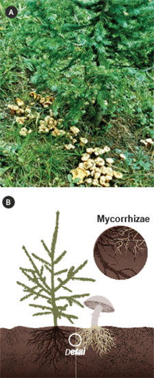
Figure 5-33 | Symbiotic relationships of plants
Many plants rely on symbiotic relationships to survive and grow in nature (A). The mushrooms under this spruce are the fruiting bodies of a beneficial fungus that has formed mycorrhizae on the roots (B). Photo credit: Thomas D. Landis
Background
Beneficial microorganisms are naturally occurring bacteria, fungi, and other microbes that play a crucial role in plant productivity and health. Some types of beneficial microorganisms are called “microsymbionts” because they form a symbiotic (mutually beneficial) relationship with plants. In natural ecosystems, the root systems of successful plants have several microbial partnerships that allow them to survive and grow even in harsh conditions (Figure 5-33). Without their microsymbiont partners, plants become stunted and often die. Frequently, these failures are attributed to poor nursery stock or fertilization, when the real problem was the absence of the proper microorganism.
As described in Section 5.2.7 (see Sources and Application of Arbuscular Mycorrhizal Fungi) it is important to consider beneficial microorganisms as part of an overall strategy to conserve existing ecological resources on the site. These strategies include the following:
- Minimizing soil disturbance
- Conserving and reapplying topsoil and organic matter
- Leaving undisturbed islands or pockets on the project site
- Minimizing use of fast-release fertilizers
On projects where soil disturbance will be minimal or where topsoil is still present and contains functional communities of beneficial microorganisms, reintroducing the organisms will usually not be necessary. However, most road projects involve severe disturbances and, therefore, healthy populations of beneficial microorganisms may be depleted or even absent. Soil compaction and removal of topsoil, which is routine during road construction, is particularly detrimental to beneficial soil microorganisms. In addition, beneficial bacteria and fungi do not survive in soil for long periods of time in the absence of their host plants and may be killed during the topsoil storage period. Reintroducing beneficial microorganisms may be an important component in establishing and maintaining native vegetation and in restoring soils.
Appropriate beneficial microorganism can be reintroduced by inoculating seeds and plants with the beneficial microorganism, or introducing the microorganism in the planting hole. Applying inoculum however, does not always result in the colonization of the root system with the beneficial organism. As will be discussed, colonization depends on the quality of the inoculum and the soil environment. Plants with well colonized root systems may establish more quickly and with less water, fertilizer, and weed control, than non-colonized plants, thereby reducing installation costs.
The two most important microsymbionts for revegetation projects are mycorrhizal fungi and nitrogen-fixing bacteria.
What are Mycorrhizae?
Mycorrhizae are one of the most fascinating symbiotic relationships in nature. “Myco” means “fungus” and “rhizae” means “root”; the word “mycorrhizae” means “fungus-roots.” The host plant roots provide a convenient substrate for the fungus and also supply food in the form of simple carbohydrates. In exchange for this free “room-and-board,” the mycorrhizal fungus offers benefits to the host plant:
Increased Water and Nutrient Uptake—Beneficial fungi help plants absorb mineral nutrients, especially phosphorus and micronutrients such as zinc and copper. Mycorrhizae increase the root surface area, and the fungal hyphae access water and nutrients beyond the roots (Figure 5-34). When plants lack mycorrhizae, they become stunted and sometimes chlorotic (yellow) in appearance (Figure 3-29 and Figure 5-34B).
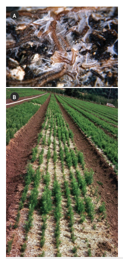
Figure 5-34 | Mycorrhizal fungi benefits host plants
Mycorrhizal fungi offer many benefits to the host plant. The fungal hyphae increase the area of absorption for water and mineral nutrients, whereas fungal mantle covers the root and protects it from desiccation and pathogens (A). Seedlings grown in nurseries soils that are low in mycorrhizae are often stunted as shown in this patchy nursery bed (B). Photo credit: Thomas D. Landis
Stress and Disease Protection—Mycorrhizal fungi protect the plant host in several ways. With some fungi, the mantle completely covers fragile root tips (Figure 5-34A) and acts as a physical barrier from drying, other pests, and toxic soil contaminants. Other fungal symbionts produce antibiotics that provide chemical protection.
Increased Vigor and Growth—Plants with mycorrhizal roots survive and grow better after they are planted on the project site. This effect is often difficult to demonstrate but can sometimes be seen in nurseries where soil fumigation has eliminated mycorrhizal fungi from seedbeds. After emergence, some plants become naturally inoculated by airborne spores and grow much larger and healthier than those that lack the fungal symbiont (Figure 5-34B). Mycorrhizal fungi form partnerships with most plant families, and three types of mycorrhizae are recognized:
- Ectomycorrhizal fungi (ECM) have relatively narrow host ranges and form partnerships with many temperate forest plants, especially pines, oaks, beeches, spruces, and firs.
- Arbuscular mycorrhizal fungi (AMF) are also known as endomycorrhizae or vesicular-arbuscular mycorrhizae. These fungi have wide host ranges and are found on most wild and cultivated grasses and annual crops, most tropical plants, and some temperate tree species including cedars, alders, and maples as well as flowering forbs use by pollinators.
- Ericoid mycorrhizal fungi form partnerships with the Epacridaceae, Empetraceae, and most of the Ericaceae; plants affected include blueberries, cranberries, crowberries, huckleberries, azaleas, rhododendrons, and sedges. Because these mycorrhizal associations involve unique species of fungi, few commercial inoculants are available and the best option is to use soil from around healthy plants.
For restoration purposes, the important thing to remember is that different plant species have specific fungal partners. ECM fungi are generally specific to one genus, whereas AMF fungi can colonize a wide range of genuses. Conserving existing topsoil and organic matter is a key practice to protecting existing populations of beneficial microorganisms. Where disturbed soils are expected, practices may be necessary to reintroduce the key microsymbionts. Applying mycorrhizal inoculants is one option, which is based on the target host plants and the site condition. Identifying whether the host plant is endomycorrhizal, ectomycorrhizal, ericoid, or non-mycorrhizal is important in selecting inoculum. Conifer seedlings, for example, require very specific ectomycorrhizal fungi for successful inoculation. Endomycorrhizal species, on the other hand, are broad in range and therefore a general mix of several endomycorrhizal species can be used for a broader range of plant species.
Sources and Application of Ectomycorrhizal Fungi
Three common sources of ECM inoculants are soil, spores, or pure culture vegetative inoculum.
Soil—Topsoil, humus, or duff from beneath ECM host plants in or near the project can be used for inoculum if done properly (Figure 5-35A). Because disturbance and exposure to direct sunlight may kill these beneficial fungi, inoculation using these sources need to be done as quickly as possible. For the best results, small amounts topsoil, humus or duff are collected from several different
locations and mixed into the soil prior to planting.
Spores—Spore suspensions are sometimes available from commercial suppliers. These spores are collected in the field from ripe fruiting bodies like mushrooms and truffles (Figures 5-35 B and C). The quality of commercial sources can be variable so it is important to verify the quality of the inoculum. It is also possible to make inoculum from spores by collecting ripe fruiting bodies of mushrooms, puffballs, or truffles from beneath healthy plants. They are then rinsed and pulverized in a blender for several minutes to make a slurry. Fungal spores do not have a long shelf life and benefit from being refrigerated and applied as soon as possible.
Pure Culture Inoculum—Mycorrhizal fungi are available commercially as pure cultures, usually in a peat-based carrier. Most commercial sources contain several different species of ECM. Because this type of inoculum is made from pure fungal cultures and does not store well, it is rarely available from suppliers.
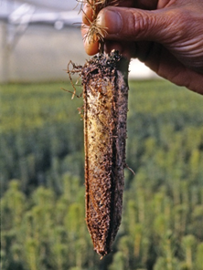
Figure 5-36 | Ectomycorrhizae fungi are visible on roots
Ectomycorrhizae are visible on plant root systems as white or colored structures with a cottony or felt-like texture. Photo credit: Thomas D. Landis
Application rates and methods for ectomycorrhizal inoculums vary by species. Because these mycorrhizal fungi are very specific to their host species, it is important to work closely with company representatives when using ectomycorrhizal inoculum. Nurseries can inoculate plants with ECM and if this service is desired, it needs to be stated in the seedling-growing contract. However, as stated above, there is no guarantee that the plants that are inoculated with have colonized roots when they are planted at the project site.
Other ectomycorrhizal fungal inoculums are applied at the time of planting with the objective to get the inoculum in contact with the plant roots. Some formulations are mixed with water and the slurry is applied to the roots of nursery stock. However, the effectiveness of many of these applications has not been verified by research under roadside revegetation conditions.
Verifying the Effectiveness of ECM Inoculation—It is fairly easy to recognize ECM with the naked eye on the root system of a seedling. The short feeder roots of the seedling is covered with a cottony-white or a brightly colored mantle or sheath over the roots (Figure 5-36). Unlike pathogenic fungi, mycorrhizae will never show signs of root decay. Sometimes, mushrooms or other fruiting bodies will appear alongside their host plants which is an indicator of the species of mycorrhizae that is present. If mycorrhizae is not visible on the roots systems, plant samples can be sent to a laboratory where they analyzed for inoculation effectiveness.
Sources and Application of Arbuscular Mycorrhizal Fungi
The two main sources of arbuscular mycorrhizal fungi inoculants include “pot culture,” (also known as “crude” inoculant), and commercially available pure cultures.
Nursery Pot Culture—With this option a specific AMF is acquired either commercially or from a field site as a starter culture, and then added to a sterile potting medium. A host plant such as corn, sorghum, clover, or an herbaceous native plant is grown in this substrate and as the host grows, the AMF spores multiply (Figure 5-37A). At maturity the shoots of host plants are removed and the substrate, now rich in roots, spores, and mycelium, is processed (Figure 5-37B). The resultant inoculum can be incorporated into growing media or planting beds before seeds are sown. This is a highly effective technique for propagating AMF in the nursery and could also be used on the planting site. For details, refer to Arbuscular Mycorrhizas: Producing and Applying Arbuscular Mycorrhizal Inoculum (Habte and Osorio 2001).
Commercial Products—Several brands of commercial AMF inoculants are available and usually contain a mix of several fungal species. Coarser-textured products are incorporated into soil or growing media, and finer-textured products are applied as wetable powders through sprayers or injected into irrigation systems. Inoculation effectiveness has been shown to vary considerably between products, so it is wise to install tests before purchasing large quantities of a specific product. Laboratories can provide a live spore count, which is the best measure of inoculum quality.
Application of AMF Inoculants—AMF inoculums typically come in a granular form with different grades of fineness. Coarse-grade products are mixed in the soil prior to sowing seed. Finer-grade inoculums, which are more expensive, may be mixed with water and applied directly onto seeds or as a root dip. Use of fine-grade inoculum through hydroseeding equipment is another way to combine AMF with seeds as they are sown. There is little research on AMF inoculation effectiveness on roadside revegetation sites.
Verifying the Effectiveness of AMF Inoculation—Unlike ectomycorrhizal fungi, AMF are not visible to the unaided eye. To verify the effectiveness of AMF inoculation, roots are stained and examined under a microscope for the percent of the root system that is colonized by AMF.
Management Considerations for Mycorrhizal Fungi
It may be helpful to work with a specialist to selecting the application rates and appropriate mycorrhizal partners for the plant species and outplanting sites. Some management modifications may be required to promote formation of mycorrhizal partnerships in the field. Fertilization is probably the most significant adjustment. Mycorrhizal fungi extend the plant’s root system to extract nutrients and water from the soil. In some cases, fertilizer applications can be reduced by half or more due to the increased nutrient uptake by mycorrhizal fungi. Fertilizer type and form are also important. For instance, high levels of soluble fertilizers may inhibit mycorrhizae. An excessive amount of phosphorus in the fertilizer may inhibit the formation of the partnership and therefore could be reduced. If nitrogen is applied, ammonium-N is better used by the plant than nitrate-N (Landis 1989). Controlled-release fertilizers are preferred because they release small doses of nutrients gradually, compared to the more rapid nutrient release from traditional products. Applications of certain herbicides, pesticides, insecticides, fungicides, and nematicides are detrimental to mycorrhizal fungi. See Inset 5-10 for an example of contract specifications for purchasing mycorrhizal inoculum.
Inset 5-10 | Example of contract specifications for purchasing mycorrhizal inoculum
Purchase of Mycorrhizal Inoculum. The mycorrhizal inoculum has a Statement of Claims that certifies:
- the date inoculum was produced
- mycorrhizal fungi species present in the inoculum
- number of propagules per pound of product, and
- the type and grade of carrier.
Product Specifications. Date of inoculum application will be within one year of production date. The storage, transportation and application temperatures of the mycorrhizae shall not exceed 90 degrees F. Inoculum must consist of at least 5 species of (choose endomycorrhizal, ectomycorrhizal or a combination of endo and ectomycorrhizal) fungi with no one species making up more than 25 percent of the propagules.
- The inoculum will contain these species: ________________________________________
- The inoculum will contain ________________________________________ live propagules per pound (Typical rates for endomycorrhizal inoculums average around 60,000 to 100,000 propagules per pound and 110,000,000 propagules per pound in ectomycorrhizal inoculums.)
- (For applications to the soil surface only) Live propagules must be smaller than 0.3mm.
- (Optional) A one ounce sample will be collected from each inoculum and sent to laboratory ________________________________________ for analysis using the standardized test to determine the number of propagules.
Application of Endomycorrhizal Inoculum to Soil Surface
- Endomycorrhizal inoculum will be applied at a rate of ________________________________________ live propagules per acre (typical rates range from 1,000,000 to 3,600,000 live propagules per acre).
- Inoculum will be applied in the same operational period as seed application.
- If inoculum is applied through a hydroseeder, it needs to be applied within 45- minutes of being mixed in the hydroseeding tank.
Application of Mycorrhizal Fungi to Planting Holes
- Mycorrhizal inoculum will be applied at a rate of ________________________________________ live propagules per seedling.
Nitrogen-Fixing Bacteria
Nitrogen-fixing bacteria live in nodules on plant roots and accumulate (fix) nitrogen from the air and share it with their host plants (Inset 5-11). Unlike mycorrhizal fungi, which are found on most trees and other plants, only certain species of plants form symbiotic partnerships with nitrogen-fixing bacteria.
Inset 5-11 | How does biological nitrogen fixation work?
The symbiotic partnership between plants and their nitrogen-fixing microsymbionts works this way:
Nitrogen fixing bacteria, present in the soil, are attracted to flavonoids secreted from the roots of host plants and invade the root cracks or deformed root hairs. In response, a root nodule appears and an environment for nitrogen bacteria is created. Within the low oxygen environment of each nodule, millions of bacteria convert atmospheric nitrogen to ammonia (NH3) through an enzyme call nitrogenase. This typically requires a relatively high amount of energy that the plant supplies to the bacteria. In return, the plant receives ammonia, which is converted to amino acids and used to synthesize proteins for plant growth. When the “nitrogen-fixing” plant sheds its leaves, or dies, the nitrogen stored in the plant’s tissues is released into the soil and becomes available to other plants. This process, part of the nitrogen cycle, is the major source of nitrogen fertility in most natural ecosystems.
The role of nitrogen-fixing bacteria and their partner plants is important in revegetating roadsides. Because nitrogen-fixing plants are often pioneer species that are the first to colonize disturbed sites, they are ideal for revegetation or restoration projects. These species help restore fertility and organic matter to the project site. Nitrogen-fixing bacteria form nodules on roots of host plants (Figure 5-38A) and accumulate nitrogen from the air (Figure 5-38B). While plants that form this association are sometimes called “nitrogen-fixing plants,” the plant itself is not able to fix nitrogen by itself. It is only through the partnership with bacteria that these plants are able to obtain atmospheric nitrogen. In this partnership, the bacteria supply the plants nitrogen, and in exchange, the bacteria is given a place to grow and carbohydrates from the plant for energy. Without these bacterial partnerships, plants are not able to make direct use of atmospheric nitrogen.
Soil on restoration sites, however, may not contain the proper species of bacteria to form a symbiotic partnership with the plant. This is particularly true for compacted subsoils. Inoculating plants ensures that “nitrogen-fixing” plants form an effective partnership to fix nitrogen. Therefore, use of nitrogen-fixing plants can be an important part of accelerating rehabilitation of degraded land.
Two genera of nitrogen-fixing bacteria that are important in revegetation are Rhizobium and Frankia. Rhizobium grow with some members of the legume family (Figure 5-39A and B) and plants of the elm family. They form nodules on the roots and fix nitrogen for the plant. Frankia are a different kind of bacteria. Frankia partner with non-leguminous plants, such as casuarinas, alders, bitterbrush, and buffaloberry (Figure 5-39C and D) and more than 200 different plant species distributed over eight families. The species affected by Frankia are called “actinorhizal” plants (Table 5-12).
Table 5-12 | Nitrogen-fixing bacteria and their plants
Nitrogen-fixing bacteria |
Family |
Subfamily |
% Nitrogen fixing plants |
Common plant species |
Rhizobium spp. |
Legume |
Caesalpinioideae |
23 |
Redbud, honeylocust |
Legume |
Mimosoideae |
90 |
Mesquite, acacia |
Legume |
Papilionoideae |
97 |
Lupine, milkvetch, black locust, clover |
Frankia spp. |
Birch |
|
Alder, birch |
Oleaster |
|
Silverberry, buffaloberry |
Myrtle |
|
Myrtle |
Buckthorn |
|
Cascara, snowbrush, deerbrush |
Rose |
|
Mountain mahogany, cliffrose, bitterbrush |
Uses for Nitrogen-Fixing Plants in Revegetation
Only a fraction of native species are nitrogen-fixing host plants. In the western United States, the most common are the lupines, vetch, bitterbrush, ceanothus, alder, and wax myrtle (Table 5-12). On nitrogen-poor sites, sowing or planting a higher proportion of these species can help a site to recover nitrogen fertility and organic matter (Figure 5-40A). The amount of nitrogen that is produced is related to the area of vegetative cover in nitrogen-fixing host plants, the productivity of the plants, and climate factors such as temperature and moisture. If percent cover of nitrogen-fixing host plants is low, then the amount of nitrogen supplied to the site will be correspondingly low (Figure 5-40B). Likewise, dry or cold conditions tend to result in slower accumulation of nitrogen. While many native and introduced nitrogen-fixing plants are attractive to pollinators, they are also attractive forage for large herbivores.
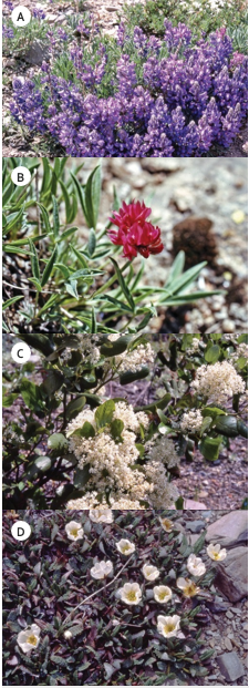
Figure 5-39 | Nitrogen-fixing plants
Nitrogen-fixing bacteria include Rhizobium that forms relationships with plants in the legume family including lupines (A) and clovers (B), and Frankia that forms relationships with other non-leguminous plants such as snowbrush ceanothus (C) and mountain-avens (D). Photo credit: Tara Luna
A plant survey of disturbed and undisturbed reference sites can indicate which nitrogen-fixing plants will do well on a revegetation project. Observing the abundance of root nodules on these plants can provide some indication whether they are fixing nitrogen.
Inoculating with Nitrogen-Fixing Bacteria
Nitrogen-fixing nursery stock with nodulated root systems generally exhibit faster early growth than seedlings than unnodulated root systems. Nursery inoculation can reduce costs in establishment and maintenance; several dollars’ worth of inoculant applied in the nursery is inexpensive compared to applying nitrogen fertilizer. Faster establishment can also lead to greater herbaceous cover that can shade out unwanted vegetation. When nitrogen-fixing plants shed leaves or dies, the nitrogen stored in the plant’s tissues is cycled into the soil and eventually taken up by adjacent plants. Early establishment of nitrogen-fixing plants accelerates natural nutrient cycling on disturbed sites and promotes the establishment of sustainable plant communities.
Note that in many cases, uninoculated seedlings may eventually form a partnership with some kind of Frankia or Rhizobium strain after they are outplanted. These may not be with optimal or highly productive bacterial partners, and it may take months or even years on highly disturbed sites. Until they become naturally inoculated, plants are dependent on nitrogen fertilizers and may become out-competed by weeds. Inoculating in the nursery ensures that plants form effective, productive partnerships in a timely fashion.
Acquiring Nitrogen-Fixing Bacterial Inoculants—Nitrogen-fixing bacteria are very specific; in other words, one inoculant cannot be used for all plants and a different inoculant strain for each nitrogen-fixing species is usually necessary. Superior strains can yield significant differences in productivity and growth rate of the host plant—in some cases over 40 percent better growth (Schmit, 2003).
Two forms of inoculant can be used: pure cultured inoculant and homemade (often called “crude”) inoculant. Pure cultured inoculant is purchased from commercial suppliers, seed banks, or sometimes, universities. Crude inoculant is made from nodules collected from roots of nitrogen-fixing plants of the same species to be inoculated. Whichever form is used, it is important to handle the inoculants with care because they are very perishable. Storing the inoculants in cool, moist conditions away from light will help maintain their viability.
Pure culture inoculants usually come in small packets of finely ground peat moss (Figure 5-41A). The inoculants are added to chlorine-free water to create a liquid slurry (allowing a bucket of tap water to stand uncovered for 24 hours is a good way to let chlorine evaporate). If a blender is available, using it to blend some inoculant in water is a good practice to ensure the bacteria will be evenly mixed in the solution. If a blender is not available, a mortar can be used. Five to ten grams (about 0.2–0.4 ounce) of manufactured inoculant can inoculate about 500 seedlings, usually exceeding the recommended 100,000 bacteria per seedling. Once seedlings begin to nodulate, nodules from their roots can serve as the basis for making crude inoculant as described below. This way, inoculant need only be purchased once for each plant species grown, and thereafter, crude inoculant can be made from nodules.
Preparing Crude Inoculant—Crude inoculant is made using nodules; each of which can house millions of bacteria. For Rhizobium, observing a brown, pink, or red color inside the nodule is usually a good indicator that the bacteria are actively fixing nitrogen. For Frankia, desirable nodules will be white or yellow inside. Grey or green nodules indicate that the structures are not viable.
To make a crude inoculant, select healthy, vigorous plants of the same species as the plants to be inoculated. If available, choose seedlings that were inoculated with select bacteria. Search for nodules with the proper color and pick them off cleanly. If possible, collect nodules from several plants and place them in containers. As soon as possible after collection (within a few hours), put the nodules in a blender with clean, chlorine-free water. About 50 to 100 nodules blended in a liter of water are enough to inoculate about 500 seedlings. This solution is a homemade liquid inoculant, ready to apply in the same method as cultured inoculant as described below. If they are to be stored, place in refrigerated conditions to maintain viability.
Applying Inoculant—It is important to apply inoculant when seedlings are just emerging, usually within two weeks of sowing. This helps ensure successful nodulation and maximizes the benefits of using inoculants. One liter of liquefied inoculant made from either nodules or cultured inoculant as per the instructions above is diluted in water. For 500 seedlings, about 5 liters of chlorine-free water is used. This solution is then watered into the root system of each seedling using a watering can. In the field, for direct seeding applications, the slurry of commercial or crude inoculant can be added to the hydroseeder tank along with the seed mix.
Management Considerations for Nitrogen-Fixing Inoculations
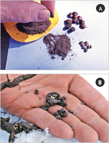
Figure 5-41 | Nitrogen-fixing bacteria are commercially available
Nitrogen-fixing bacteria are commercially available as pure culture inoculant, often in a carrier (A), or can be prepared by collecting nodules from roots of plants in the wild (B). Photo credit: Tara Luna
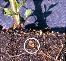
Figure 5-42 | Nitrogen-fixing bacteria will multiply as inoculated plants grow
After successful inoculation, nitrogen-fixing bacteria will multiply on the root system as plants grow. The circle points to a visible Frankia nodule on an alnus seedling. Photo credit: Tara Luna
Verifying the Nitrogen-Fixing Partnership—Allow two to six weeks for indications that seedlings have formed a symbiotic partnership with nitrogen-fixing bacteria. Signs include the following:
- Seedlings begin to grow well and are deep green despite the absence of added nitrogen fertilizer
- The root systems give off a faint but distinctive ammonia-like scent
- Nodules are usually visible on the root system after about four to six weeks Figure 5-40A and Figure 5-42), and nodules are pink, red, or brown (for Rhizobium), or yellow or white (for Frankia)
Post-Planting Care—Several factors are of primary concern when using inoculants for nitrogen-fixing bacteria:
- Fertilization—The use of nitrogen-fixing bacterial inoculant likely requires some adjustments in fertilization. Excessive nitrogen fertilizer will inhibit formation of the partnership.
- Water quality—Excessive chlorine in water is detrimental to Rhizobium and Frankia. The water source may need to be tested and a chlorine filter used if excessive chlorine is a problem.
- Micronutrients and soil quality—Some nutrients are necessary to facilitate nodulation, including calcium, potassium, molybdenum, and iron. Excessively compacted soils, extremes of pH or temperature also inhibit nodulation.
Other Beneficial Microorganisms
In nature, communities of bacteria, fungi, algae, protozoa, and other microorganisms in the soil make nutrients available to plants, create channels for water and air, maintain soil structure, and cycle nutrients and organic matter. A healthy population of soil microorganisms can also maintain ecological balance, preventing the onset of major problems from viruses or other pathogens that reside in the soil. The practice of protecting and reestablishing beneficial micro- organisms is key for revegetation. As a science, however, the use of beneficial microorganisms is in its infancy. Although thousands of species of microorganisms have been recognized and named, the number of unknown species is estimated to be in the millions. Almost every time microbiologists examine a soil sample, they discover a previously unknown species (Margulis et al 1997). Conserving, maintaining, and creating healthy soils will help to create and sustain the natural populations of beneficial microorganisms.
5.2.8 TOPOGRAPHIC ENHANCEMENTS
Introduction
Topographic enhancements are alterations to the roadside landscape designed to improve the growing environment for plants. Topographic enhancements are important when site resources such as topsoil, organic matter, and water are limited (Section 3.10). It is often better to concentrate limited resources in key areas where resources can be most effective rather than spread them across the larger project area and dilute them to the point of having little benefit to reestablishing native vegetation. An additional benefit of topographic enhancement features is that most are designed to capture water related to road drainage. This improves water quality by reducing peak-flow water to watersheds and capturing sediments.
Topographic enhancement integrates three components into the roadside design: soil improvement, site stability, and water harvesting (Figure 5-43). Soil improvement can occur when limited topsoil and organic matter are strategically used to create growing areas with optimum rooting depth (Section 3.8.2, see Rooting Depth). Stable landforms are created that reduce surface erosion and increase slope stability (Section 3.8.5 and Section 3.8.6).
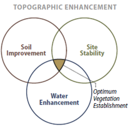
Figure 5-43 | Topographic enhancement strategies
Optimal topographic enhancement for establishing vegetation occurs when the roadside design includes soil improvement, site stability, and water capture treatments. It is important to consider topographic enhancement strategies early in project design.
Water harvesting can result when local topography is modified to capture runoff water and concentrate it in areas where it can be used by plants (Section 3.8.1, see Road Drainage) (for background on water harvesting, see Fidelibus and Bainbridge 2006). The integration of these three components will determine the success of a topographic enhancement design.
Topographic enhancement strategies are considered during the road planning stage and the design of any features are in collaboration with the planning engineer. There are many types of topographic enhancement structures. This discussion is not exhaustive but is rather intended to introduce the designer to a variety of structures that can be installed during road construction to enhance the establishment of native plants.
Planting Pockets and Microcatchments
When terraces are filled with growing media (topsoil or amended subsoil) and planted, they are referred to as planting pockets. Planting pockets are designed to have adequate soil depth and good water holding capacity to store intercepted water and support the establishment of planted seedlings. The surface of the planting pocket is in-sloped to capture water and sediment and the face of the pocket is protected from surface erosion using a mulch (Figure 3-15).
Fill slope microcatchments are structures that capture runoff from outsloped road surfaces and compacted shoulders into terraces and berms where it can be used for plant growth (Figure 3-14). Microcatchments include storage basins and berms. Berms are typically 4- to 8-inch-high obstacles placed on the contour. They are formed from soil, woody debris (logs), or manufactured products such as straw wattles or compost berms. Manufactured products and woody debris are “keyed” (partially buried) into the soil surface to prevent water from eroding under the structure. Compost berms are continuous mounds of compost that can slow water and filter sediments. Seedlings can be planted immediately above berms or obstacles to access captured water. Unless species that propagate vegetatively are used in these structures, it is important to avoid planting where sediment will bury the seedling.
Planting Islands
Planting islands are used where resources, such as topsoil and organic amendments, are limited. They are designed into such revegetation projects as obliterated roads, view corridors, disposal sites, staging areas, and other highly disturbed sites. The strategy behind planting islands is to create areas of ideal growing environment for tree seedlings that replicates the natural topography and tree distribution observed in the surrounding landscape.
Islands can be created by excavating to a depth of several feet and backfilling with either topsoil or compost-amended material (Figure 5-44). Alternatively, compost and other soil amendments (including lime and fertilizers) can be spread over planting islands at the depth needed to amend the soil profile and mixed thoroughly through the soil with an excavator or backhoe. After planting, mulch can be applied across the surface of the entire island. Planting islands will generally occupy less than a quarter to a third of the entire site, leaving the remainder as “inter-island.” The inter-islands will be much less productive than the planting islands. Grass and forb plant communities are therefore more suited to these areas (Figure 5-45).
Amended Ditches
The purpose of amended ditches is to treat road runoff before it reaches live channels. Amended ditches are designed for areas where there is not enough room along the roadside for vegetated swales but they differ in that they are not terraced, nor as wide. Because of their high infiltration rates, these structures retain more sediment and runoff as compared to typical ditches.
Amended ditches are designed to have high infiltration rates and good water storage capacity. These soil characteristics allow road runoff water, originating from low to moderate rainstorm events, to be absorbed and stored in the soil below the ditch. As rainfall intensities increase, the amended ditches become saturated and convey water. To stabilize the channel surface from downcutting during high rainstorm events, the ditches are designed to support a continuous vegetative cover. The organic matter that is added to the ditches during construction, not only keeps the soils open and supports vegetative cover, has been shown to sequester road pollutants (Grismer et al 2011).
One method of constructing an amended ditch is to place 6 inches by 3 feet layer mixture of shredded wood/compost along the ditchline and incorporating it into the soil to a depth of 18 inches with an excavator (Figure 5-46). The shredded wood/compost mixture is produced by mixing 3 parts shredded wood with 1 part compost. The shredded wood adds structure and drainage while compost adds slow
release nutrients for establishing and maintaining vegetation. Compost reduces or eliminates the need for fertilizing which is important because fertilizers placed in ditchlines may enter stream courses and decrease water quality.
It is important to establish a vegetative cover on the ditches prior to when heavy precipitation periods are expected. Grass seeds, composed of species appropriate to the site, are applied to the amended ditches and covered with weed-free straw or shredded wood as soon as the ditches are constructed. If seeding is done in the summer, in areas where rainfall is low, it may be necessary to irrigate to encourage the quick establishment of vegetation. The schedule of watering depends on the site however, a simple rule is to water when the surface of the soil, beneath the straw, just begins to dry out. Watering can be coordinated with the dust abatement operation.
Biotechnical Engineering Structures
Topographic enhancement includes a variety of engineering structures that integrate vegetation into the design. These include vegetated retaining walls, brush layers, vegetated riprap, and live pole drains. Attention to the quality of topsoil is important in most biotechnical engineering structures. For instance, the quality of topsoil and how it is placed in vegetated retaining walls is critical for establishing vegetation (Figure 5-47). Where riprap is to be vegetated, it may require a deep layer of high quality composts cover placed over and between the riprap (Figure 5-48).
Runoff Strips and Constructed Wetlands
Figure 5-49 | Constructed wetlands are effective at capturing runoff water
Constructed wetlands capture water from roadside runoff and filter sediments before water enters perennial streams. Constructed wetlands can create favorable habitat for unique flora and fauna. Photo credit: David Steinfeld
Runoff strips are catchment structures constructed in areas where intermittent concentrated road drainage occurs. These are typically at the outlets of culverts or in road drainage dips. Runoff strips capture concentrated runoff into small ponds or catchment basins. These areas can be planted with riparian species, such as willows (Salix spp.) and cottonwoods (Populus spp.), or wetland species, such as rushes (Juncus spp.) and sedges (Carex spp.). Runoff strips are placed in draws or concave topography and are composed of engineered impoundment barriers, using riprap, logs, or gabion baskets, which store water from runoff events. The barriers have spillways (low points in the structure) and are keyed into the sides to ensure that concentrated water does not erode around its sides. Where runoff strips are on gentle gradients, constructed wetlands may possibly be developed (Figure 5-49).
Back to top
5.3 OBTAINING PLANT MATERIALS
Obtaining the appropriate species, seed source, and stocktype for a revegetation project involves advanced planning and lead time. Obtaining genetically adapted materials, for example, may involve targeted collections of plant materials near or in the general geographic area of the project site several years prior to project implementation. The group of implementation guides in the following section focuses on three types of plant materials: seeds, cuttings, and plants. Section 5.3.1 covers how to determine the amount of wild seed to collect, wild seed collection methods, cleaning techniques, storage conditions, and quality testing. Methods for collecting the stems of willows and cottonwoods in the wild (as well as several other native species that propagate vegetatively) are described in Section 5.3.2. Salvaging plants from the wild and replanting them on project sites are described in Section 5.3.3.
For most projects, the collection of wild seeds, cuttings, or plants is not sufficient to meet project objectives. To increase plant materials, wild collections need to be sent to native plant nurseries for propagation. Section 5.3.4 outlines the basic steps necessary to work with nurseries in establishing seed production beds for increasing seed banks of grass and forb species. Producing large quantities of cutting material of willow and cottonwood species can be accomplished by establishing stooling beds from wild collections at nurseries, covered in Section 5.3.5 and Section 5.3.6 describes how to work with nurseries to obtain high quality bareroot or containerized seedlings.
5.3.1 COLLECTING WILD SEEDS
Introduction
Wild seeds can be collected from native stands of grasses, forbs, shrubs, trees, and wetland plants found in or near project sites or other locations as determined via processes described in this report. The primary objective for wild seed collection is to obtain genetically appropriate, locally adapted seeds for starting nursery-grown plants (Section 5.3.6), nursery seed production (Section 5.3.4), and/or occasionally to sow directly on a disturbed site. Because seed and seedling propagation hinges on the availability of wild seeds, propagule collection is one of the first major tasks of developing a revegetation plan and can be initiated as early as possible while a project is in the planning stage. Depending on the purpose, the lead-time for collecting wild seeds could be up to three to four years before sowing or planting the project site (Figure 5-50). Seed collectors need to get approval from Project Engineer if harvesting is planned in ROW adjacent to an active roadway. Following safety practices near traffic). This lead-time is important because it requires multiple growing seasons to establish plants in the nursery or in grower’s seed increase field.
Grass and forb species are often seeded directly onto disturbed sites. In order to obtain enough seeds for direct seeding, wild seed collections may be “increased” in nursery production or agricultural seed fields (Section 5.3.4) depending on the size of the revegetation project. Trees and shrub seeds, however, are not typically sown directly on disturbed sites but are instead sent to nurseries for seedling propagation, then outplanted one to three years later depending on the stocktype and seedling size specifications. Seeds from wetland genera, such as sedges (Carex spp.) and rushes (Juncus spp.), are often collected for both seed and seedling production purposes.
Revegetation plans are seldom finalized before wild seeds are collected. At a minimum, planning identifies revegetation units, describes reference areas, determines species to propagate, and involves completing a survey of the construction site to determine the amount of area to be revegetated. The quantity and location of wild seed collection are based on these early surveys.
Collecting wild seeds can be expensive. Multiple collection trips are often needed to monitor and collect populations because each species has a small ripening window, and most species do not ripen at the same time. In addition, many species do not consistently produce seeds from year to year, requiring multiple years to generate adequate foundation collections.
Before collecting wild seeds or setting up collection contracts, it is advisable to the Natural Resources Conservation Service, determine if other genetically appropriate species seed sources are already available for the project. Often local agencies or commercial producers will have seeds in storage for many of the species growing near the project area, especially species used for reforestation.
Develop Timeline
Wild seed collection is one of the first tasks to consider when beginning revegetation planning. Three to four years are often necessary in order to locate, collect, clean, and test wild seeds, and still allow the nursery or seed producer enough lead time for plant and seed production (Figure 5-50).
Seed collection contracts are typically awarded prior to the growing season to provide the contractor enough time to locate and assess the collection areas, source populations, and potential seed crop. Seeds are monitored periodically and collected when ripe. Wild seed harvests are cleaned, tested and certified, and stored prior to shipment to the nursery or grower for seed increase.
Determine Wild Seed Needs for Seed Production
Wild seed collection and the nursery seed increase contracts are often developed simultaneously because the information needed for wild seed collection is based on the expected seed yields of the seed increase contract. This section describes how to calculate the amount of wild seeds to collect based on the amount of seeds expected from a commercial seed producer. The designer will most likely need to work directly with the contracted seed producer to better understand the potential seed yields of a specific crop grown in a specific location.
The amount of uncleaned wild seeds to collect for seed propagation contracts usually requires the following information (used in the calculations in Figure 5-51):
- Seed needs
- Years in seed production
- Sowing rates
- Annual seed yields
- “Cleaned-to-rough cleaned” seed percentage
The quantity of wild seeds to collect can be determined from this spreadsheet. Pearly everlasting (Anaphalis margaritacea) is used in this example.
Seed Needs—The total seeds needed for each species on a revegetation project is based on the total planned revegetation acreage, seedlot characteristics (germination, purity, seeds per pound), site limitations (e.g., how well seeds will survive), and the desired seedling densities after seeds have germinated. Refer to Section 5.3.4 (see Determine Seed Needs for Seed Production) for methods to calculate how many seeds are needed for each species in a revegetation project.
Years in Seed Production—Every species has its own seed production characteristics. For example, species such as blue wildrye (Elymus glaucus) and California brome (Bromus carinatus) produce high seed quantities the first and second year, then level off or decline in years three and four. Species such as fescues (Festuca spp.) and Junegrass (Koeleria spp.) yield few seeds in the first year, but seed harvest levels increase to full production in the second or third year. For these species, consider scheduling a minimum of two years for seed production. Refer to Section 5.3.4 (see Determine Seed Needs for Seed Production) for discussion of first- and second-year yields for some commonly produced species.
Given proper storage conditions (Section 5.3.4, see Seed Storage), seeds of many species can be stored for several years or longer and still maintain good viability. For this reason, seed production does not have to occur all in one year. For projects that have several years lead time, maintaining production fields gives the designer more flexibility.
Sowing Rates—Commercial growers use a minimum amount of clean wild seeds (e.g., a foundation collection) to establish a seed increase field to produce a given quantity of seeds. While these rates differ somewhat between seed producers, general sowing rates for some commonly propagated species in the western U.S. are shown in Table 5-15 and Table 5-16.
Annual Seed Production Yields—The amount of seeds that are produced annually varies by species, geographic location of the fields, weather conditions, and experience of the seed producer. Understanding what yields can be expected from seed producers will determine how many acres will be under production. Average seed yields for some species used in revegetation in the western U.S. are presented in Table 5-15 and Table 5-16.
Cleaned-to-Rough-Cleaned Seed Ratio—Foundation seed collections from the wild can include stems, chaff, and flower parts (Figure 5-52). It is a good practice for seed collectors to clean this material as much as possible before it is sent to a seed extractory for final cleaning. The amount of non-seed material can be a substantial part of the wild seed collection weight. “Cleaned-to-rough-cleaned” seed ratios (Table 5-13) can help calculate the extra weight of seeds to collect in the wild to compensate for seed cleaning. Dividing the desired amount of cleaned seeds by this ratio will yield the amount of wild seed that needs to be collected. This information can be provided by the seed extractory or specialists familiar with the cultivation practices of a certain species.
Table 5-13 | Typical ranges of “cleaned-to-rough cleaned” seed recovery percentages
To obtain the amounts of “rough” seeds to collect, divide the amount of cleaned seeds needed by the “cleaned-to-rough cleaned” factor. For example, if 5 pounds of cleaned seeds of prairie Junegrass (Koeleria macrantha) are needed, a minimum of 12.5 pounds of rough cleaned seeds should be collected ( 5 / 0.40 = 12.5 ) The cleaned recovery percentage can vary greatly depending on seed collection method (e.g., stripping seed versus clipping seed heads which increases trash impurities.
Chart based on Pacific Northwest Region Forest Service seed collections data.
|
Common name |
Scientific name |
Cleaned-to-rough cleaned factor |
Bluebunch Wheatgrass |
Pseudoroegneria spicata |
0.25 to 0.33 |
Idaho Fescue |
Festuca idahoensis |
0.33 to 0.50 |
Prairie Junegrass |
Koelaria macrantha |
0.20 to 0.40 |
Squirreltail |
Elymus elymoides |
0.20 to 0.25 |
Yarrow |
Achillea spp. |
0.20 to 0.25 |
Sandberg Bluegrass |
Poa secunda |
0.33 to 0.40 |
Blue Wildrye |
Elymus glaucus |
0.50 to 0.65 |
Determine Seed Needs for Seedling Production
The quantity of wild seeds to collect for propagating seedlings at plant nurseries will be based on an estimate of the quantity of seedlings needed, the percent seed germination, the percent seed purity, seeds per pound, and the nursery factor. An estimate of germination, purity, and seeds per pound can be obtained through published sources, seed inventories, or from seed extractory managers. The nursery factor is a prediction of the percentage of viable seeds that will become “shippable” seedlings. Each nursery has developed a set of factors based on culturing experience and practices. It is good practice for nursery managers to supply nursery factors for each species or information on the amount of seeds to collect to meet the seedling order.
Nursery factors are often less than 50 percent.
Using the following equation, the amount of wild seed to collect can be estimated:
Quantity of seedlings needed
[ ( % of germ / 100 ) * ( % purity / 100 ) * ( seeds / pound ) * ( nursery factor / 100 ) ]
Locate Plants in the Wild
Potential collection areas are identified during the vegetation analysis phase (Section 3.6.1). General collection locations can be established by the designer with consult of a botanist or revegetation specialist familiar with the local vegetation. Contracts often require seed collectors to identify individual collection areas for approval prior to collection.
Effective wildland seed collections incorporate genetic principles and guidelines for ensuring local adaptation and genetic diversity in the resulting seedlot. These include collecting seeds from multiple, well-distributed locations within an established seed zone or other biogeographically defined area. Genetic diversity may be enhanced by collecting seeds in approximately equal quantities from approved collection areas, and collecting from a large number of widely spaced or unrelated parent plants per area (over 50 is optimal).
For the Designer
The seed collection methods and processes described in this section require a high level of expertise and familiarity with the target species. Designers should seek input from botanists, geneticists, and revegetation specialists as needed.
Plant populations growing in unusually harsh or challenging environment conditions (e.g., weedy sites) may be good candidates to consider due to natural selection pressures and genetic adaptations that may produce offspring with improved fitness and competitive ability (Strauss et al 2006; Leger 2008). Within any site, generally no more than 50 percent of the seed crop should be collected in a given year, and repeated collections in subsequent years are to be minimized or avoided to preserve viability of native plant population and dependent wildlife, including pollinators (Section 3.13.2).
Collection sites are kept free of any plants listed as noxious weeds by the State Agency or any species on the Federal Noxious Weed List because of the potential of seed contamination. Once located, the collection sites can be documented in GPS and/or marked with flagging at a point easily visible from the road used to access the site. It is expected that landowner or manager permission would be obtained when seed collection is to be conducted outside of the project area or agency-administered lands.
Collect Seeds
Inset 5-12 | Stages of grass seed maturity
For grasses, the stages of seed ripening can be determined by squeezing a seed between the thumb and forefinger. The stage of seed maturity is broadly defined by the following response:
- Milk stage—A milky substance is secreted, indicating an immature seed lacking viability.
- Soft-dough stage—Seed has a doughy texture, indicating it will have low germination and viability if collected.
- Hard-dough stage—No excretion of dough or milky substance when squeezed. Seeds are collected at this stage. Seeds can be collected at the transition between soft-dough and hard- dough stages. If collection occurs between these stages, seeds should not be stripped from the plant. Instead, seed heads should be cut and placed in collection bags where seeds will continue to mature.
- Mature—Seeds in this stage are usually too hard to bite. Collection should begin immediately because seeds can dislodge from the stem at any time.
Visually sound and sufficiently mature seeds are the only seeds ready for collection. Seeds are considered sound when the embryo has developed normally and there is no evidence of insect, disease, climatic, or other types of damage. Seed maturity in plants with fleshy fruits (many shrub and some tree species) often corresponds with changes in color (e.g., color changes from green to red, blue, purple, or white), taste (higher in sugars when mature), or hardness (fruit softens with maturity). Wind-dispersed seeds, which include many of the conifer species, usually change from green to brown when ripe. For grass species, a quick test for seed maturity can be determined by how seeds respond to being squeezed (Inset 5-12). A more effective method is to cut the seed and identify the development of the embryo under a hand lens or microscope. Because seed ripeness is influenced by the local weather and microclimate, determining seed ripeness often requires several monitoring trips to the field prior to collection.
Seed collection techniques are tailored to the species being collected. Grass and forb species, for example, can be hand-harvested by stripping or clipping stems just below the seed heads and placing them in collection bags or containers. Effective collection containers are made of materials that allow airflow, such as paper or fine mesh. Plastic bags or plastic containers are generally not effective. Other methods of collecting grass and forb seeds include mechanical flails and vacuums. While these methods can increase seed harvesting rates significantly, they are best done on nearly pure stands of a single species to avoid contaminating the seedlot with more than one species. Some forbs, such as lupine (Lupinus spp.), have indeterminate inflorescence, which means they continuously bloom, starting from the bottom of the flower head and progressing to the top (Figure 5-53). These species present a problem in seed collection because seeds ripen continuously through the growing season. Seeds from these species are often obtained by making multiple trips to the field and collecting seeds from the lower portions of the stem without disturbing the flowers or immature seeds above. Multiple collection trips may also be required if there is substantial variation in seed ripening among different type of microsites.
Figure 5-53 | Seed ripens throughout the season for some plant species
Species such as lupine (Lupinus spp.) have indeterminate inflorescence bloom and set seeds all summer. Seeds ripen first at the bottom of the stem and continue to ripen up the stalk as the season progresses. Photo credit: David Steinfeld
Seeds of many shrub species are often collected by holding a bag or tray under the plant and shaking the plant or flailing the branches with a stick or tennis racket. While the seeds of some shrub species ripen and remain on the seed head, others, such as Ceanothus spp., shatter when mature and are to be collected as soon as they ripen. Because multiple collection trips can be expensive, an alternative approach is to enclose the seed head of each plant in a mesh or paper bag before the seeds have begun to ripen. At the end of the season, ripened seeds will have dispersed into the bags which can be processed or transferred to other containers. It is good practice to avoid collecting seeds or seed-bearing fruits from the ground, although in some cases paper or cloth may be placed under the plant to catch the seeds (e.g., forbs and shrubs whose seeds shatter upon maturity). The seed collection contractor should specify the methods that will be used for collection.
Site location and other details of the collection can be documented on a form similar to the NRCS data collection form. Key information to record includes the following:
- Species (scientific name)
- Geographic location information (GPS point) or latitude/longitude or UTM coordinates
- Date of collection
- Name of collector
- Number of populations collected
- Elevation
- Road project name
For the Designer
State certification agencies can provide seed certification and other quality assurance services to agencies and other clients to help ensure that seed and plant products meet accepted standards. These services may be especially useful when an agency is unable to monitor all stages of plant material production from seed/ cutting collection through seedling propagation and seed increase. Seed certification regulations and procedures are regulated by the Association of Official Seed Certifying Agencies (AOSCA).
It is good practice to clearly identify each seed collection bag or container in the field using a label similar to the Forest Service identification tag shown in (Figure 5-54). These tags are generally available at Forest Service district offices or seed extractories. To ensure the identity of the seedlot in case the tag is accidentally removed during handling or shipping, it is a good idea to duplicate the tag and place it inside the collection bag. Consider grouping field collections into seedlots prior to sending these collections to the seed extractory for cleaning. Individual collections within a species are generally only maintained as separate seedlots if the objective is genetic testing or research. The expense of cleaning, packaging, and keeping records of a multitude of collections outweighs the necessity of storing them separately.
Clean and Test Seeds
A good practice is to clean wild seed collections to a standard that can be uniformly applied through seed sowing equipment for seedling production or seed increase. The method of application may determine the type of cleaning required, e.g., hand broadcast may need less processing than drill seeding. Seed extractories have the experience and equipment to clean wild seeds of many plant species that are frequently used in revegetation projects throughout the U.S. Seed cleaning is typically completed in two to three steps: (1) removing seeds from cones or seedpods (conifer species and some hardwood tree, shrub, and forb species), (2) detaching structures from seeds, and (3) removing all non-seed materials from collections. Removing seeds from most conifer cones involves using tumbling equipment to allow seeds to separate from scales. Some conifer species and many shrub and hardwood species require specialized equipment to break open the seedpod without damaging the seeds. Detaching seed structures involves the mechanical removal of awns (grasses) and fleshy structures, wings or other appendages. Once seed structures are detached, non-seed materials, including stems and chaff, can be removed from the collections, leaving high purity seeds (e.g., greater than 90 percent) or some user-specified level depending on the species and intended use of the particular seedlot. Seeds sown in seed increase fields with high precision equipment, for example, are generally cleaned to a higher purity level than seeds that will be hand sown or spread as mulch directly on a project site.
For the Designer
See the list of Association of Official Seed Analysts (AOSA) members and their contact information.
Seed extractories will dry, package, and store seeds, as well as test seeds on-site or send seed samples to a testing facility. Note that seed extractories cannot improve a poorly collected seedlot. Seed extractories cannot completely remove weed seeds, damaged seeds, or immature seeds from a collection, nor separate seeds from different crop species mixed in a seedlot. Removing contaminants from a seedlot becomes increasingly difficult and expensive as the size, shape, density, color characteristics of the undesirable material are more similar to the seed of the target species. Prior to collecting wild seeds, it is important to contact the seed extractory manager to discuss which species will be cleaned and for what purpose. Seed extractory managers are valuable sources of information on collection and care of a variety of native species seeds.
Cleaned seeds can be tested for germination, purity, seeds per pound, and presence of noxious weeds (Inset 5-13) by an approved seed testing laboratory (Inset 5-14). Testing involves collecting representative samples from each seedlot. Seeds are usually stored in large sealed drums or bags. If there are multiple containers per seedlot, samples from each container are to be drawn in proportion to the size of the container. Because the amount of seeds needed for testing may vary by species and laboratory, consider contacting seed testing facilities prior to submitting samples for special instructions. Ideally, seed sampling is conducted by a person who is trained and certified in this work, and preferably by a third party if contracts or purchasing documents are in place that contain seed quality requirements and specifications.
Seed viability usually decreases with longer durations in storage. It is good practice to conduct seed testing every few years, or at least the year before it is sown, to obtain the most accurate germination information. Copies of seed tests can be retained in contract files and on seed inventories.
5.3.2 COLLECTING WILD CUTTINGS
Introduction
Using cuttings can be a viable alternative to planting seedlings or sowing seeds to reestablish native vegetation. Vegetative material is collected from stems, roots, or other parts of donor plants and directly planted on the project site or sent to a nursery to produce rooted cuttings. The potential to produce roots from vegetative cuttings varies by species—from easy to propagate to extremely difficult. The most common species propagated from vegetative cuttings are shrubs typical of riparian ecosystems and some trees. Many deciduous species that grow well in riparian settings, such as willows (Salix spp.) and cottonwoods (Populus spp.), have a high success rate when propagated from cuttings. Shrubs with characteristics desirable to pollinators include ninebark (Physocarpusspp.) and twinberry honeysuckle (Lonicera spp.). Most temperate evergreen trees and shrubs, however, only root under very controlled environments with specialized propagation techniques.
The intent of this section is to provide the designer with a greater understanding of how to select and collect cuttings in the wild. The primary focus will be on the species in the genera Salix and Populus, because these are these are most frequently used for direct planting of cuttings. With some exceptions, such as Ribes and Cornus species, most other temperate tree and shrub species can be sent to the nursery for the production of rooted cuttings before they are installed on project sites. In tropical and subtropical areas, a wider variety of species can be collected as wild cuttings. If temperate species other than willow and cottonwood are considered for propagation, nurseries can be contacted to determine the best methods for selecting, cutting, and handling the material.
Cuttings can be obtained from wild collections or from cultivated stands of donor plants, called stooling beds. Stooling beds are established at nurseries or other agricultural facilities from wild collections. In this section, the focus is on how to obtain cuttings from wild locations. The discussion of producing cuttings from stooling beds is provided in Section 5.3.5.
Inset 5-13 | Seed tests
Modified from Tanaka 1984
Seed testing is used to evaluate seedlot quality and provide information for determining sowing rates for seed and seedling production. Test results also provide a basis for determining seed costs when based on Pure Live Seeds (PLS), so are important for commercial seed trade, as well as for monitoring longevity and changes in germination or viability from harvest through cleaning and storage. Methods used for seed testing are based on rules of the Association of Official Seed Analysts (AOSA). A number of tests are normally conducted on each seedlot to evaluate physical and biological seed characteristics. See a list of AOSA Labs and their contact information.
Physical Characteristics
- Purity—Purity tests are used to determine the percentage by weight of four components: pure seeds of the desired species, seeds of other species, weed seeds, and inert matter, such as stems, chaff, scales, and small stones (Note: A purity test is based on 250 seeds and noxious seed on 2,500 seed sample). Graminoid seeds with more than 10 to 15 percent inert matter will be difficult to apply through a rotary seeder or rangeland drill. Purity tests verify the seedlot contains no “prohibited” noxious weed seeds and meets or exceeds standards for “restricted” or “other weed seeds” according to state standards for Certified Seed. Because each state has different lists of prohibited and restricted noxious weeds, it is important to request an “All-States Noxious Weed Exam.” While not prohibited or restricted by the state, some aggressive non-natives found through seed testing may still pose a threat to native plant communities.
- Moisture content—Seed moisture content for most species is determined by oven-drying. Seed samples are weighed and heated at 105° C (221° F) for 16 hours, then weighed again. Seed moisture is expressed as the percentage of the weight of the water lost over oven-dry weight. Electronic moisture meters are also frequently used but are not as accurate as the oven-drying method. They give rapid measurements when checking moisture in a large number of seedlots. Moisture tests are important for determining the storability of seeds. Typically, seed moistures for long-term storage are best at less than 10 percent.
- Seeds per pound—Seeds per pound is the weight of a given number of seeds of the desired species and does not include seeds of other species or weed seeds. The method weighs 100 seeds of 8 random samples and converts the values to number of seeds per pound.
Biological Characteristics
- Germination— germination test conducted in a controlled environment is the most reliable method for testing seeds. At least 400 seeds from the pure-seed component of the purity test are used in the test. Depending on the species, the seeds are usually divided into 4 replicates of 100 seeds each and chilled (stratified) for a pre-determined period and placed on trays in controlled germination chambers. At 7-day intervals, the number of seeds that have germinated (when all essential structures appear normal) are counted (AOSA 2002).
- Tetrazolium staining—Although controlled-environment germination tests are reliable, they are also time-consuming, particularly for those species requiring chilling. A rapid method of estimating viability is tetrazolium (TZ) staining. This test is preferred if results are needed immediately or if species to be tested have unknown chilling or germination requirements, which is often typical of many native species (Rauch 2006). The TZ test requires seeds to be immersed in 2,3,5-triphenyl tetrazolium chloride. Living cells stain red as the chemical is reduced by dehydrogenase enzymes to form a stable red triphenyl formazan, which is insoluble in water. Seeds are cut and the embryos that are red-stained are counted as viable seeds. This test is useful for native species that produce seeds that are dormant and will not germinate without after-ripening (that is, seeds placed in an environment where they will continue to ripen) or without special germination enhancement treatments (stratification, scarification, gibberellic acid, etc.). In these cases, germination tests usually report out lower viability rates than actually exist. Because TZ tests measure the percentage of live embryos, they typically give a better indication of potential germination percentage. Parallel TZ and germination tests can be conducted to determine how many of the ungerminated seeds are viable or dead.
- X-ray—At least 400 seeds, divided into 4 replicates of 100, are X-rayed and evaluated for the presence of mature embryos, insect damage, filled seeds, damaged seeds, and other seed characteristics that could affect germination. X-raying is a fast and relatively inexpensive test, but not as accurate or informative as germination or TZ tests. It’s also useful to conduct on a seed sample collected prior to harvesting to decisions on the timing of harvest initiation, or on post-harvest samples to evaluate the need for seed conditioning treatments to improve seed quality.
Inset 5-14 | Seed Processing, Testing, and Storage—USFS Bend Seed Extractory
From left: Various seed processing equipment at USFS Bend Seed Extractory; Loading grass seed into a brush cleaner.
Photo credit: Jim Barner, US Forest Service
The US Forest Service Bend Seed Extractory (Bend, OR) is dedicated to seed, and only seed. Established in 1952, the Extractory is a full service state-of-the art seed processing and storage facility for all native species, including conifers, hardwood trees and shrubs, grasses, forbs, and succulents. Their staff also provides training and consultations to designers and other revegetation specialists on seed use planning, collection methods, and seed handling, testing, and storage requirements.
Processing Seed— Prior to use or storage, wild collected seed will generally need to be hand-screened, stripped, or mechanically cleaned to remove impurities such as excess chaff, stems, leaves, trash, dirt, and seeds of non-target species. The Bend Seed Extractory has a complete line of specialty and small lot cleaning equipment to handle the broad array of native species that are collected by National Forests and other federal, state, and county agencies (including FHWA and state DOTs). Each year the Bend Extractory processes 10,000-15,000 pounds of seed from more than 2,700 different species. Any seedlot size can be accommodated.
Seed Testing—After cleaning, Bend Extractory conducts seed quality testing on every seedlot, including purity, seeds per pound, percent filled seed, and seed moisture content. At the client’s request, additional testing (e.g., seed viability and percent live or dead seed) can be arranged at other approved facilities.
Storing Seed—The Bend Extractory also provides storage facilities, regardless of whether the seed is cleaned in-house or by other processors. Extractory staff work with clients to select the optimum seed storage — granary (55° F), cold storage (34° F), or freezer (14 ° F). Prior to storage, cleaned seed is sealed in 6 mil plastic to ensure longevity. Stored seed can be quickly removed from inventory at any time, and shipped to other facilities or field locations at client’s request.
Wild cuttings are used in revegetation projects when seeds or seedlings are difficult to obtain, when seeds germinate poorly in the nursery, or when cuttings are needed for biotechnical engineering objectives. Seed yields can be low for many species due to a variety of reasons, including poor pollination, disease, and insect damage. Some species, such as pinemat manzanita (Arctostaphylos nevadensis) and Pacific yew (Taxus brevifolia), produce seeds that can be very difficult to germinate in nursery environments. Other species, which include many tree species, produce seeds irregularly and there may be many years between seed crops. Some seeds are difficult to collect either because they are inaccessible (in the upper portions of trees) or the window of seed collection is very narrow (e.g., Ceanothus spp.). For these species, starting plants in the nursery from rooted cuttings may be the only viable and eco- nomical alternative (Section 5.3.6, see Select Stocktypes). Vegetative cuttings can also be very useful in biotechnical engineering projects when installed as living structures. These projects combine the physical strength of cuttings with root strength of establishing plants to increase surface and slope stability (Section 5.4.3).
For the Designer
It is critical that vegetative cuttings are harvested during the period when donor plants are dormant, especially if the material is to be stored for any length of time prior to outplanting.
Also remember that cuttings, like seed, are living material and are to be handled as such during collection and outplanted to ensure good plant survival and growth.
The ratio of benefits to limitations can be an important consideration when deciding whether to use cuttings over seeds or seedlings. Some factors that can limit the successful establishment of cutting material are the accessibility and availability of donor plants, how well the material roots (rooting potential), and how well the material survives once it has rooted. A common oversight when working with cuttings is forgetting that this material is alive and subsequently handling the material poorly during collection and outplanting. Another oversight is collecting cuttings outside of dormancy, when plants are actively growing. Neglecting either of these facts often leads to failed revegetation projects. This implementation guide covers the major factors that are important to consider when working with wild cuttings.
Develop Timeline
Locating cutting areas in the field might seem like a simple task, but it can be difficult when faced with such realities as land ownership, accessibility of the cutting areas, winter weather conditions, and poor quality of plant materials. For these reasons, considering a lead time of several years can be good practice for projects requiring large quantities of wild cuttings (Figure 5-55). On large projects, sufficient lead time allows for the location of potential collection sites and testing of the rooting potential of cutting material. If cuttings are used to propagate stooling beds (Section 5.3.5), which are recommended for large projects, cuttings need to be collected at least two years or more to establish the beds. If the material is to be used to produce rooted cuttings at a nursery, good practice is to collect the material at least a year prior to installation. When the materials are cut for direct installation on a project site, the cuttings will be made in the fall through winter prior to planting.
Locate Cutting Areas
Inset 5-15 | How to tell the difference between male and female willows and cottonwoods
Identifying the sex of dioecious plants is easiest when they are flowering or fruiting. Willow (Salix spp.) catkins may appear before, during, or after new leaves appear in spring. Identifying anthers in male catkins (A) and pistils in female catkins (B) with a hand lens is relatively easy, especially with practice. Female plants can easily be identified when the cottony seeds are mature (C). During the winter dormant season, it is possible to identify the sex of dormant cottonwoods by dissecting floral buds, although this is more difficult with willows. Detailed instructions on how to sex willows and cottonwoods can be found in Landis et al (2003).
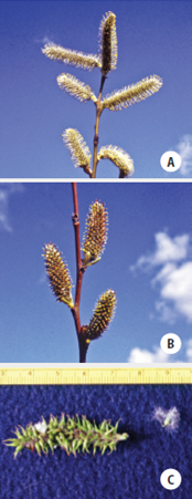
The vegetation assessment during the planning phase (Section 3.6.1) is an opportunity to locate potential sources of cuttings. During this field survey, cutting sites are mapped and assessed for the following characteristics:
Proximity and Accessibility—Good sources for cuttings are not always found within the project site, so it is necessary to survey over large areas within the seed zone (Section 3.13.2, see Seed Zones and Transfer Guidelines). Sometimes good collection sites are miles away from the project, which can substantially increase costs. However, the benefits of collecting quality plant materials far outweigh the additional transportation costs. The large size and weight of cutting materials often limits collections to areas adjacent to and accessible from roads. Poor road conditions during the winter, a season when cuttings are most likely to be collected, can be important considerations in site selection because of the potential of being closed by snow or winter road damage. It is often possible to collect quality cutting material within the right-of- way clearance, which is identified during the vegetation assessment.
Ownership—Some of the best collection sites may be on private lands. It is expected to obtain permission from the landowner prior to collecting. Cutting from areas located on Federal, State, and local government managed lands can be coordinated through these agencies. Observe collection standards for size and quantity dictated by the landowners. Consider taking care to avoid over-harvesting a source population.
Viability—The quality of the cutting material is an important criterion for determining the suitability of a collection site. Determining the viability of the collection material is an activity that can be completed prior to selecting the collection site (Section 5.3.2, see Determine Rooting Potential)
Genetic Considerations—It is important to determine if the species to be collected is monoecious (male and female reproductive parts on the same plant) or dioecious (male and female reproductive parts on different plants). If the species is dioecious (Inset 5-15), such as willow or cottonwood, it’s desirable to collect cuttings from both male and female plants in approximately equal amounts to promote genetic diversity and long-term species viability and sustainability. Determining the sex of donor plants is easiest during the reproductive period when floral structures are fully formed and most visible, typically early spring. (See Inset 5-15). This might add an additional year to the timeline. To further preserve genetic integrity, it is recommended to collect from a minimum of 50 donor individuals within the seed zone or other biogeographically defined area (Section 3.13.2). Differentiating between genetically distinct individuals within an area can be difficult with clonal species, such as willows and cottonwoods, because what often appear as a group of individual plants are actually offshoots (ramets) of a single parent plant.
Diameter Size—The project objectives, which can be assessed when a collection site is evaluated, will determine which stem diameters should be collected (NRCS 1997).
Small diameter—Small-diameter materials, called branched cuttings or whips, average less than 1.0 inch in diameter and are derived from the fine branches of healthy, dormant donor plants. This material is tied into long bundles to form live fascines (Section 5.4.3, see Live Fascines) or laid on the surface of the soil to form brush mattresses. Live fascines are placed in shallow trenches on slope contours to function like small water and sediment collection dams, or they are placed at an angle to the slope to facilitate slope drainage (Section 5.4.3). Small-diameter materials are also used for branch packing and to vegetate geogrids and rock gabions. Additionally, small-diameter materials are used for rooted cutting production at nurseries. The typical diameter size preferred by most nurseries ranges from ³⁄₈ to ½ inch.
Medium diameter—Medium-diameter cutting materials are used to make live stakes (Section 5.4.3, see Live Stakes), which range in size from 1.0 to 3.0 inches in diameter. Stakes are tamped into the ground at right angles to the soil surface to secure small slumps, live fascines, and erosion control materials. Joint plantings are stakes that are driven between rocks or riprap; it is good practice that they be greater than 1.5 inches in diameter and several feet long. Materials ranging from to 2.5 inches are used to revegetate live crib walls. Effective crib wall cuttings are long enough to reach 4 to 6 feet back to the end of the wall.
Large diameter—Larger-diameter materials called poles are used as dormant post plantings to stabilize streambanks. The diameter of these poles range from 3 to 5 inches and they are 7 to 9 feet long. Large poles are not always easy to obtain in the wild but can be produced from nursery stooling beds.
Cutting Footage—The total length of cuttings available for harvest can be estimated for each potential cutting area. This can be roughly calculated by evaluating 10 to 20 donor plants and estimating the average length and number of usable stems (by diameter size categories) that could be obtained from each. The average length is then multiplied by the estimated number of plants in the cutting area to obtain a total estimated cutting footage. This will be the high end of an estimate because most landowners are likely to place a restriction on the amount of cuttings that can be harvested at one time. For example, a landowner might limit the amount of cuttings that can be taken from an area to 25 percent in a riparian area. The cutting footage would be 25 percent of the total length of the cuttings.
Determine Rooting Potential
Not all cuttings will root and become established plants when installed on a project site. The success rate of those that do become plants is dependent on the percentage of cuttings that form roots when placed in an ideal growing environment (or the rooting potential) and the percentage of viable cuttings (those that root) that become established after a growing season (or the survival potential).
Rooting potential is analogous to germination percentages obtained from seed testing. Seed tests are performed under uniform, ideal growing conditions and are a measure of the potential of seeds to germinate (Section 5.3.1, Section 5.3.4 and Section 5.4.1). Rooting potential is similar to germination in that it assesses the potential of cutting materials to produce roots under an ideal rooting environment. The potential of cutting materials to initiate roots is the basis for determining how many cuttings to collect and the density to plant. For example, if the rooting potential of a specific collection is low, more cuttings will need to be planted at closer spacing to compensate for those cuttings that do not root.
Root potential tests have been developed for measuring the viability of nursery-produced plants (Ritchie 1985), but there are no standardized tests for determining the rooting potential of cuttings. Labs that offer seedling quality tests might, on request, use or adapt the root growth potential tests developed for seedlings to assess the rooting potential of vegetative materials. Inset 5-16 describes one possible method for assessing rooting potential.
Rooting potential is affected by several plant factors, the most important of which are species, genotype, date of collection, portion of plant collected, age of material, condition of material, and preparation techniques.
Species—A small percentage of temperate tree and shrub species will root consistently from cuttings. Those that root well can be cut and used directly on revegetation projects. Other species initiate roots only under controlled nursery environments and might best be grown into rooted cuttings before they are planted on a project site. A list of commonly used native species in the western US that root from cuttings is provided in Table 5-14.
Table 5-14 | Common species that can be propagated from vegetative material
| Species |
Vegetative material |
Rooting Potential |
In field |
In greenhouse |
Willows Salix spp. |
Stems |
Easy* |
Easy* |
Cottonwoods Populus spp. |
Stems |
Easy |
Easy |
Snowberry Symphoricarpos albus |
Stems |
Easy to Mod1 |
Easy to Mod1 |
Pacific ninebark Physocarpus capitatus |
Stems |
Easy to Mod1 |
Easy to Mod1 |
Black twinberry Lonicera involucrata |
Stems |
Easy to Mod1 |
Easy to Mod1 |
Douglas spirea Spiraea douglasii |
Stems |
Mod1 |
Mod1 |
Salmonberry Rubus spectabilis |
Stems |
Mod1 |
Mod1 |
Quaking aspen Populus tremuloides |
Roots |
Poor |
Mod |
Redosier dogwood Cornus sericea |
Stems |
Mod2 |
Mod |
Chokecherry Prunus virginiana |
Roots |
Mod2 |
Mod |
Golden currant Ribes aureum |
Stems |
Poor |
Mod2 |
Woods’ rose Rosa woodsii |
Stems |
Poor |
Mod2 |
Manzanita Arctostaphylos spp. |
Stems |
Poor |
Mod |
Several species, such as S. scourleri, are difficult to root
For the Designer
It is important to collect cuttings either from wild sources or in a nursery setting during the dormant period of a given species.
Genotypes—Within each species, there is variability in rooting potential. Some donor plants (genotypes) will have greater rooting potential than other plants. Unless tests are conducted, it is hard to know which donor plants are optimal rooters.
Date of Collection—The optimal time to collect cutting material is during plant dormancy. For most willow and cottonwood species, this period extends from mid-fall, after the donor plant drops its leaves, to bud swell in late winter to early spring. It is safe to assume that if donor plants have lost their leaves, cuttings will be at their highest rooting potential.
Planting unrooted cuttings within the dormancy period is not always possible because most construction work is curtailed during winter months. If unrooted cuttings must be planted outside the dormancy period, establishment rates will significantly decrease. Several alternative measures can be taken: collect cuttings during dormancy and keep in cold storage until they can be installed (Section 5.3.2, see Long-Term Storage); collect cuttings outside the dormancy period and plant more cuttings to compensate for the anticipated attrition (Section 5.3.2, see Determine Survival Potential); or use rooted cuttings in lieu of unrooted cuttings.
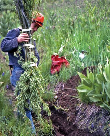
Figure 5-56 | Harvesting actively growing material can lead to poor results
Collecting cuttings outside of plant dormancy, as was done for the project shown in this photograph, can lead to extremely poor results. If this practice is considered, rooting potential tests can be performed first to confirm success rates. Photo credit: David Steinfeld
Collecting plant materials outside the dormancy period has been tried in biotechnical engineering projects with varying degrees of success (Figure 5-56). Species that root easily, such as most willows (Salix spp.) and cottonwoods (Populus spp.), will root from cuttings collected outside dormancy, albeit at very low success rates (Steinfeld 2002, 2005). In some instances, however, this may be the only option available to the designer, who may consider it a last resort. When these are the circumstances, collecting outside the dormancy period is most effectively done with an understanding of how establishment rates will be affected and whether the overall project objectives will be met. For large projects, it is important to conduct rooting and survival potential tests (Inset 5-16) several years before cuttings are installed so that the appropriate amount of cuttings can be collected and planting densities can be determined (Section 5.3.2, see Determine Survival Potential). An alternative to dealing with low survival potential of wild cuttings is to establish stooling beds (Section 5.3.5).
Portion of Plant—Most cuttings are taken from stems and branches. However, the rooting potential for some species is greatest when cuttings are taken from roots (Table 5-14).
Ageof Material—The rooting potential changes with the age of the donor plant. Many species have greater rooting potential from new growth, while others perform better when materials are collected from older branches or stems. Species that have a higher rooting potential in the older portions of the plant make excellent live stakes because the size of the material is often large enough to withstand being driven into the ground (Darris and Williams 2001).
Condition of Material—Vegetative material from donor plants can be affected by insects and disease, which can severely reduce rooting potential (Section 5.3.5).
Preparation Techniques—Several practices can potentially enhance rooting potential. One method involves soaking dormant cuttings in water immediately prior to planting. Schaff et al (2002) found that soaking black willow (Salix nigra) for up to 10 days in water doubled the survival rates of large diameter, dormant cuttings over unsoaked cuttings. Some designers have reported an increase in rooting potential of cuttings collected outside the dormancy period by stripping leaves from stems, while others have found this ineffective (Steinfeld 2002). Soaking cuttings in hormones can increase rooting in some species (Shaw 2004), although it can be detrimental to others (Darris and Williams 2001). Testing rooting treatments on a small scale through rooting potential tests can be conducted prior to applying these methods on a larger scale.
Inset 5-16 | Testing method for determining rooting potential for willow and cottonwood species
Testing the viability of willow and cottonwood cuttings takes much of the guesswork out of establishing plants through this method of propagation. While it is not a common practice in revegetation work, testing the viability of cuttings can be considered for similar reasons as seed testing. Most designers would not think of applying seeds on a project without first testing for germination, purity, and seeds per pound, yet they do not think twice about using cuttings without having tested them first. This oversight can lead to higher costs, as well as low establishment rates.
There are no established testing procedures for assessing rooting potential of cutting materials. Until these tests are established, the following means of root assessment is presented which can be used to compare results from year to year. Ideally, a controlled environment, such as a greenhouse, is the best place to conduct a rooting potential test since the best temperature range is between 65° and 75° F. Using bottom heat or rooting hormones is not necessary; in fact, for some species, it can be detrimental for rooting (Darris and Williams 2001). Where a greenhouse is not available, use an indoor space where relatively constant temperatures can be maintained. Effective grow lights provide at least 12 hours of light per day.
Consider randomly collecting 15 samples, at a minimum, from different donor plants at each collection area. The samples would ideally be of the same size and treated in a manner similar to what would be expected under normal operations. For example, if stakes with diameters between 2 and 3 inches are to be collected in August and soaked for 10 days before planting, then the cuttings used for the tests would be of similar size, collected in August, and soaked in the same manner, and planted. Prepare each sample by cutting them into 12-inch lengths. Stick them 3 inches apart in pots that are at least 16 inches deep, filled with 1 part peat to 4 parts perlite. It is good practice to ensure that cuttings are stuck so that two buds are exposed above the media. After planting, water the pots and set them in their testing location. At weekly intervals, observe the cuttings and note the status of the leaves developing from the buds. At 28 days, record how many cuttings have developed new leaves, gently remove the media from around the cuttings, and lightly wash the stems. Viable cuttings will likely have developed roots during this period. Record how many cuttings did not initiate roots (refer to the cutting on the left in photograph below). For those cuttings that did establish roots, a quantitative estimate of root initiation can be measured by removing the roots from the stem and weighing the new roots or counting the number of new roots for each cutting.
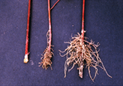
To interpret this data, assume that any cutting that did not initiate roots or develop foliage during 28 days probably will not immediately initiate roots in the field. A comparison of average root weights or number of roots between testing samples can indicate which collection sites or treatment methods will produce the best rooting materials, or if additional sites need to be located to meet genetic guidelines and broaden diversity. Those test samples with high average root weights will likely perform better than those with lower weights.
Determine Survival Potential
Not all cuttings that initiate roots under ideal testing conditions will establish when outplanted into field conditions on a project site. The percentage of viable cuttings that root and survive one year after planting is called the survival potential. The survival potential is controlled by climate, soils, planting methods, and maintenance practices for each project. It can be determined though field testing conducted prior to installing cuttings or estimated from previous field experience on similar sites using unrooted cuttings, rooted cuttings, or planted seedlings.
Climate—Survival potential is strongly influenced by the water loss potential of the site (Section 3.8.3). Sites with low moisture stress during root initiation (typically spring through early summer) will have high survival potentials. The longer that cuttings can initiate and grow roots without being under moisture stress, the greater the potential for survival. Climates with high humidity during root initiation occur in riparian areas.
Within a project area, survival potential often changes with aspect and microsite variation (e.g., true riparian zone verses upland zone). Cuttings subjected to hot, dry conditions of south aspects typically will have a lower survival potential than north aspects. Survival potential also increases in areas that have occasional summer rainstorms that wet the soil profile. Survival potential may decrease in more upland planting zones given the greater depth to the water table.
Soils—Survival potential is affected by soil water storage and accessibility (Section 3.8.2). Soils with low water-holding capacity will have lower survival potential than those with high water-holding capacity. Installation of cuttings on compacted soils will result in lower survival than loose or tilled soils. Areas that have high water tables during the growing season, such as slumps, seeps, and springs, will have higher survival potential for riparian species.
For the Designer
Good soil-to-stem contact is one of the most, if not the most critical factor in determining high survival and plant vigor.
Installation Methods—Compensations can be made for sites with poor soils or dry climates. One option is to install longer cuttings. Studies have shown that higher survival rates and greater vegetative growth can be achieved with longer cuttings (Rossi 1999). This is especially important on drier sites, because longer cuttings can access deeper soil moisture. Cuttings up to 2 feet in length have been shown to produce better survival and growth on harsher sites (McElroy and Dawson 1986; Rossi 1999). In areas where freeze-thaw potential is high (Section 3.8.5, see Freeze-Thaw) shorter cuttings have a greater likelihood of being pushed out of the ground before they can form roots to anchor them in place. Survival rates are also affected by the quality of planting methods. For example, there can be a significant decrease in survival when cuttings are planted without good soil–to-stem contact and many large air pockets. Section 5.4.3 covers the different methods of installing cuttings.
Plant Maintenance—Survival potential can also be increased if the plants are maintained during the first year after planting, including the control of competing vegetation and protection from animal browse (Section 5.5).
Determine Cutting Needs
Once the survival and rooting potential have been determined, the quantity of cuttings to collect can be calculated. The information needed for determining cutting quantities and cutting spacing (density) is as follows:
- Rooting potential
- Survival potential
- Target plant density
- Area to plant
- Desired established plant densities
- Length of cuttings
An example of how to calculate cutting quantities and planting spacing is shown in Figure 5-57. In this example, the project objective is to stabilize the slope by installing willow stakes. In the short term, this practice will increase slope stability by physically “pinning” the surface soil. The primary benefit to slope stability, however, will develop over time as the roots of the establishing willows begin to tie the soil particles together and increase soil strength. The desired spacing between established plants is 6 feet for most shrub species, but may be wider for cottonwood and willows depending on the site and project objectives. When inventories are taken one year after planting, there should be an established plant approximately every 6 feet (D), or approximately 303 established plants for the entire planting site (E).
To achieve the desired density of established plants, consider determining how many cuttings to plant and the average spacing between installed cuttings. This determination is based primarily on the rooting and survival potential (Section 5.3.2, see Determine Rooting Potential and Section 5.3.2, see Determine Survival Potential). If these are unknown, cutting needs can be based on the desired number of plants per area, with a significant buffer added in for projected losses. In this example, the rooting potential was 68 percent based on rooting potential tests. The survival factor was estimated to be around 35 percent from previous experiences on similar sites. These factors are used in the equation shown in Line F to calculate the number of cuttings needed to install. To obtain 303 established plants, it would be necessary to install approximately 1,271 cuttings. This is approximately four times the number of established plants. It is necessary to install this many to compensate for the number of cuttings that either do not root, or that root or do not survive the summer. The planting spacing is calculated using the equation in Line I. It is good practice to install cuttings at half the distance of the desired established plant spacing. Because the site conditions in this example are harsh, the cuttings will need to be planted deeply to access soil moisture. For this reason, the cutting lengths are approximately 2.5 feet. Multiplying 2.5 feet by the number of cuttings needed (F) gives the total length of cuttings to be collected (H). Knowing that 3,178 feet of cuttings are needed, the number and location of cutting areas can be selected from a cutting area map and a contract can be developed.
Long-Term Storage
If cuttings are not installed immediately, long-term storage will likely be necessary. Dormant cuttings collected in the fall or winter and stored until the following spring or summer are best held in refrigerated units. The optimum temperatures for long-term storage range between 28 to 31 degrees F. Freezing temperatures prevent disease and curtail respiration, thereby increasing cutting viability. If freezing is not possible, then storing cuttings at temperatures between 33 and 35 degrees F will likely maintain cutting viability for several months.
For long-term storage, cuttings are best when relatively free of leaves and other material that might mold in storage. They can be packaged in plastic or storage bags to help ensure that they will not dry out. Wrapping cuttings in moist burlap, especially if cuttings are not frozen, is typically not an effective approach. Diseases could potentially develop that will rot the stems.
Develop and Administer Contracts
A good plan that includes the location of cutting sites and how the cuttings will be treated, transported, and stored will be the basis for the development of a collection contract. Contract terms could specify the following:
Cutting Locations—A map or GPS locations can identify cutting areas and specify an estimated range of cutting quantities (Section 5.3.2, see Locate Cutting Areas). If the contractor elects to collect from other areas, then these areas can be approved prior to cutting. For each cutting area, the percentage of the donor population that can be collected could be specified. Typically, this is no greater than 25 percent of the population. Donor populations are most viable when not over-harvested.
Dates of Collection—The contract could specify a period of time that cuttings be collected (Section 5.3.2, see Determine Rooting Potential). Collecting outside this time period could be discussed in advance with the designer.
Collection Size, Lengths, and Quantities—Quantities could be specified for each size category. For example, if material is to be used for stakes, then a specification might require 200 stakes, 18 inches long, with a range of diameters between 1.0 inch and 3.0 inches.
Collection Methods—The contract could identify how the contractor will collect the cuttings. For example, it could state how the contractor will identify which end of a stake is basal and which is terminal. This is typically done by cutting the basal end of each stake at an angle. The contract could also specify how the cuttings will be packaged or bundled. Contracts often call for all stakes to be aligned with basal ends of the cuttings in the same direction. Bundle sizes or weights could be specified. Good bundles are light enough to be transported by one person (45 pounds or less). The contract could also state that the bundles should be securely tied or bundled together for hand transportation.
Source Identification—Each bundle could be identified with an identification tag such as the seed label described in Figure 5-54, which specifies the species, collection location, elevation, and date of collection among other information.
Special Treatments—Special measures, such as soaking and use of anti-desiccants, could be stated in the contract. If soaking is required, then the location of the soaking area could be identified on a map (Section 5.3.2, see Determine Rooting Potential).
Temporary Storage and Transportation—The contractor could address how cuttings will be temporarily stored when the weather is warm or dry. Cuttings are best when not allowed to dry out once they are collected. Temporarily storing in shaded areas covered by plastic sheets or wet burlap are acceptable methods. Delivery of cuttings is best done when the approach used does not allow the cuttings to dry. Closed transportation or covering with plastic for long distances could be considered.
5.3.3 COLLECTING WILD OR SALVAGED PLANTS
Introduction
Wild seedlings, commonly referred to as wildlings, are indigenous plants growing in their native habitat (Therrell et al 2006). They are naturally reproduced outside of a nursery but can be transplanted directly into a restoration site or into a nursery for culturing and future use. The collection and use of wildlings in native plant restoration can be a viable alternative to direct seeding, nursery seedlings, or rooted cuttings. As with wild cutting collections (Section 5.3.2), wildlings can be used where it is difficult or impossible to collect or use seeds for plant production because of the following (Priadjati et al 2001; St John et al 2003):
- The plant either does not produce seeds or produces seeds very infrequently
- Seeds are often unfilled or non-viable
- Seeds have a very narrow collection window
- Seeds have already dispersed prior to collection planning
- Insects or animals are a problem with collection
There are several advantages to using wildlings in restoration plantings. Unlike cuttings, wildings can be available immediately with little to no transport costs, and no direct nursery costs if installed shortly after collection. They can be an effective strategy for obtaining a large number of seedlings of known origin relatively quickly. Also, large wildlings provide “vertical relief” (visual prominence) more quickly to a site than other methods and, depending on the species and environment, will establish and spread quickly (Hoag 2003). Use of wildlings reduces the risk of introducing non-native organisms such as weeds and pathogens (Therrell et al 2006). If reproduction of the plant is more successful via rhizomes (e.g., sedges), transplanting wildlings may be the most efficient and effective method for reestablishing these species (Steed and DeWald 2003). In addition, if plant propagation is difficult from seeds or rooted cuttings, use of whole plants may be the only alternative for a particular species.
For the Designer
Note that removal of wildlings creates a disturbed area that may require mitigation and, at a minimum, monitoring for invasive species introduction and spread. Wildling harvest is best considered when a vegetated area is going to be impacted by construction.
Transplanting of wildling plants, however, can be unsuccessful for a number of reasons. Wildlings often grow in stressful conditions and do not recover from transplanting shock as quickly as cultivated seedlings. Wildlings often have smaller, coarser root systems than cultivated seedlings or heavier taproots that are not easily removed from soil in their entirety (St John et al 2003). Successful transplantation usually requires experience, skill, proper handling, ideal temporary storage, and proper care of the plant both before and after transplanting.
Develop Timeline
Although wildling plants may provide an opportunity for quick establishment of larger plants on restoration sites, several factors considered in the planning process could impact their availability. Determining suitable locations that can provide the number of plants required is a good early step. If large quantities of plants are necessary, it may take several years to identify these locations. Once sites are identified, one or two seasons of plant preparation prior to removal, transport, and transplanting may be required (Section 5.3.3, see Collection and Handling).
Wildling plants may be removed from their native site and either transplanted immediately or transported to a nursery, potted, and cultured for future outplanting. Transplanting following removal may occur if the plant source is an undisturbed area outside the restoration site. If plants are removed prior to site disturbance or if additional time is needed for production of sturdy plants, culturing in a nursery for a specified period of time may be necessary. Lead time of one to two years may be necessary for nursery-assisted wildlings depending on the situation. This lead time may include contract procurement and administration for both collection and nursery culturing.
Locate Wildling Collection Areas
Potential sources for wildling plants can be identified through field surveys during the vegetative assessment phase (Section 3.6.1) Sites with high potential for damage to soil resources or the plants that are to remain are likely best avoided. Sites could be located on maps, and both plants and sites assessed for the following traits:
Accessibility—Proper handling of wildling plants during removal and transport is a critical factor in ensuring survival. Smaller seedlings of some species (sagebrush) may be handled successfully similar to bareroot seedlings. In other cases, roots may require protection if the rootball is not totally contained in soil. Plants may be heavy if the rootball is intact. Therefore, it is necessary that collection sites be accessible by roads. Because most collections will be taken in fall or early spring, it is also necessary to determine whether road conditions at these times of year will preclude collection.
The best collection areas may not always be found within the project site, so large areas surrounding the project may need to be surveyed for plants. Costs will increase substantially if it is necessary to transport plants for long distances.
Land Ownership—It is good practice to obtain permission to remove plants from either the private landowner or public land management agency, when applicable. Additionally, potential future problems can be avoided by obtaining Federal or State permits, if needed in a timely manner(Hoag 2003).
Viability—If possible, areas of healthy forest or rangeland could be designated as collection sites (Priadjati et al 2001). Healthy sites contain vigorous and adequately sized material with a minimum number of unhealthy plants (St John et al 2003). Stunted needles, off-color foliage, and poor annual growth are indications of stress; it is likely best to leave these plants uncollected. Plants are most effectively removed from sites that show good regeneration over the area (Hoag 2003). It is good practice to determine the viability of the collection material and timing of use (Section 5.3.3, see Determine Transplanting Versus Nursery Culture) prior to selection of the collection site. It is important to transplant wildlings into similar growing environments. For example, plants growing under shade are best placed back into a shaded environment to achieve optimum viability.
Genetics—One of the disadvantages or limitations of using wildlings, or any form of asexual propagation, in restoration is the potential to restrict the genetic diversity of the plant population. As adequate population sampling is important to maintain this diversity, it may be advisable to identify several sites over a large area from which to collect within the seed zone. Collecting many plants over a large area will help capture both inherited and environmental variation. However, it is important to choose donor sites carefully so that they are reasonably similar to conditions of the outplanting site.
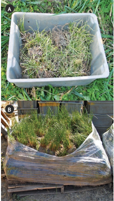
Figure 5-58 | Salvaged wetland plants
Wetland plants are often salvaged from areas that are planned for disturbance. Removing plants from wetland settings can be difficult due to wet soils and massive root systems of many species. The heavy weight of these plants makes transportation and handling difficult. Tubs (A) are used for hand-transporting to planting sites, and pallets (B) have been used for large quantities. Photo credit: David Steinfeld
Prior to collection, it is necessary to determine whether species are monoecious (male
and female reproductive structures on the same plant) or dioecious (male and female reproductive structures on different plants). If the species of interest is dioecious, both male and female plants will need to be collected in somewhat equal proportions to ensure that installed populations can persist into the future via sexual reproduction. If one of the objectives for using dioecious species is to promote, restore, or increase species, then consider locating target plants when reproductive phenology is evident, which is typically spring through summer.
Determine Transplanting Versus Nursery Culture
Although cost may be the biggest deciding factor in whether wildlings are collected for immediate transplant or growing in a nursery, other factors could enter into the decision in the restoration plan.
Timing—It is good practice to transplant wildling plants s into their new location as quickly as possible. If plants are to be collected from sites outside the disturbed area, these can potentially be removed and transplanted to the restoration site within the same time frame. However, if plant removal is part of a salvage operation where plants are located within the area of disturbance, then plants could be transported to a nursery or similar growing situation. Plants could be transplanted into pots and maintained until the appropriate outplanting season.
Species—Some plant species have characteristics that are more conducive to direct transplanting from one site to another. Plants that spread underground or with stolons will generally perform well, for example, although dry, compacted sites will slow the rate of spread significantly (Therrell 2006). Species that recover quickly from root damage, such as willows (Salix spp.) and cottonwoods (Populus spp.), will also perform well when large plants are needed quickly. These types of plants may lend themselves easily to transplanting within the same time frame as removal.
Plants with taproots, such as conifers and many shrubs, and plants with long, brittle horizontal roots, such as heather or vine maple, are difficult to transplant. Consider taking special care during removal to extract as much of the roots as possible. To ensure a higher success rate, further culturing in an optimal environment following removal may provide a healthier, more viable plant for outplanting.
Size and Availability—If wildling plants of the target species are plentiful and appropriately sized on undisturbed sites, immediate transplant during the appropriate season is feasible. However, if available wildlings are smaller than desired, an additional one or two years of nursery culture may provide a better plant for colonization of the site.
Certain plants have the ability to root by layering, such as pinemat manzanita (Arctostaphylos nevadensis). If entire plants are not plentiful, portions of individual plants can be removed and cultured in a nursery for outplanting the following year.
For the Designer
Harvesting wildlings during the dormant season can significantly reduce plant stress and increase transplant survivorship and growth.
Collection and Handling
Date of Collection and Timing of Transplanting—The season during which collection and transplanting occur has been shown to dramatically affect the survival and growth of wildling plants (Yetka and Galatowitsch 1999). Plants allocate carbohydrates and nutrients during various phases of phenological development. Different levels of tolerance to transplanting stress during the year are the result of physiological needs shifting among shoot and root growth, flowering and seed production, and storage. In addition, seasonal variation in environmental factors, such as soil moisture and temperature, can affect planting establishment (Steed and DeWald 2003).
Timing of collection will depend on whether the wildlings are to be transplanted in the same time frame or cultured in a nursery. If wildlings are to be transplanted into the restoration site following collection, the chances for survival will increase for most species if operations occur in winter to early spring. The seedlings are dormant during this period and can handle the stresses associated with transplantation. There is also less chance of damaging new roots that are initiated during the spring and fall. In addition, planting early extends the period for root growth prior to soil-drying in summer.
Collection could occur in either fall or spring if wildlings are to be cultured in a nursery. However, if plants are collected in the fall, consider taking care to avoid excessive root damage because plants will not be dormant. Due to the perishable nature of wildlings, the timing of collection could be coordinated with the nursery to ensure that the facilities, supplies, equipment, and labor are available following harvest (Figure 5-58) (St John 2003). Once collected, it is good practice to transplant plants immediately into containers.
Genetics—Collection of wildlings can consist of a single plant, a clump, or several pieces of a plant that have rooted through layering (NRCS 1997). A quality collection of individual plants is large enough to ensure adequate population sampling. A minimum of 50 plants from within the same seedzone as the restoration site is recommended.
Source Identification—Every collection could be identified with a tag which specifies the species, collection location, elevation, and date of collection (Figure 5-54).
Quality and Size—Only healthy, turgid, moderately vigorous and adequately sized wildlings could be collected for transplanting or nursery culturing. Unhealthy or stressed plants are best avoided.
Although species dependent, successful transplantation typically increases as plant size decreases (St John 2003). Transplantation of large shrubs and trees is usually unsuccessful. Their root-to-shoot ratio is unbalanced, and these plants often do not survive transplantation shock. Transplantation of larger willows, sedges, or herbaceous material into riparian zones, however, maybe appropriate depending on the vegetative competition and other establishment conditions (Hoag 2003; Steed and DeWald 2003).
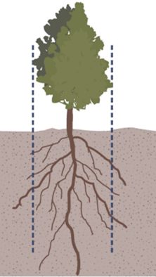
Figure 5-60 | Salvage as much of the root ball as possible
Plants can be excavated from the soil using the drip line (dashed lines) as a guide.
Handling, Transport, and Storage—Collection of wildling plants will be most successful if the soil is moist during plant removal. If precipitation has not occurred, irrigation prior to lifting would be desirable. Removal and transplantation is best conducted in the mornings on cool, cloudy days when the plant is fully turgid.
A tile spade or similar flat-bladed shovel is the best tool for small to medium plant removal. Using the “dripline” of the plant as a guide, make shovel cuts with the blade as perpendicular to the surface of the ground as possible because maintaining an intact ball of soil around the roots is important (Figure 5-59 and Figure 5-60). Root morphology could also be considered in this process. Roots growing in deep soils or arid soils will tend to grow down rather than laterally. Roots growing in shallow soils will tend to spread laterally, requiring a much larger area of disturbance (Therrell 2006).
The shovel, and hands, can be used to lift the root ball gently out of the hole while attempting to keep the root ball intact. Hand pruners can be used to cut away woody roots that do not come free with the shovel. The root ball can then be transferred to a suitable container (large bucket, pot, burlap, or plastic bag) for transport to the transplanting site (Therrell 2006). If wildlings are to be transported to a nursery, consider placing plants in plastic bags in coolers. Plastic bags can also contain moistened towels or similar material if roots are not covered with soil.
A tree spade can be used if larger plants are to be excavated and transplanted (Figure 5-61). The factors important for using a tree spade are that the terrain is accessible to the tree spade equipment (slope gradients less than 20 percent), soils are relatively free of cobble-sized rock fragment, and soils are moist. In this operation, planting holes are created first, then plants are excavated, moved, and replanted. The size of the plant to be transplanted depends on the soil volume that can be removed by the tree spade. Typically plants up to 6 feet tall can be transplanted with success. Taller trees can be irrigated into the soil to improve survival. Using a backhoe has also been successful in transplanting large willow clumps (Hoag 2003).
It is good practice to transplant wildlings into their new location as quickly as possible, with minimal to no storage time. All vegetative material is best kept cool and moist during the process. If wildlings are transported to a nursery, the plants could be kept in a cooler and transplanted into pots within one to two days of collection.
Survival Potential
As with rooted cuttings (Section 5.3.2, see Determine Survival Potential), not all wildlings will become established and thrive following transplantation. Survival is controlled by climate, soils, planting methods, and maintenance practices on the project.
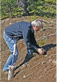
Figure 5-62 | Transplant wildlings immediately after collection
Transplant wildlings immediately following collection to minimize moisture stress.
Photo credit: Thomas D. Landis
Climate—Water loss potential (Section 3.8.3) is probably the main determining factor for survival on many sites in the western United States. Sites with low moisture stress during root initiation (spring through early summer) and sites that have the potential for longer root initiation periods will have higher survival.
Within a project area, aspect can also affect root initiation and survival. Transplanted wildlings subjected to hot, dry conditions on southern aspects have a lower potential for survival than those on cooler northern aspects.
Soils—Survival of wildlings is affected by soil water storage and accessibility (Section 3.8.2). Soils with low water-holding capacity or compacted soils will have lower survival than those with high water-holding capacity and greater porosity.
Planting Methods—Good transplantation techniques will improve the survival rates of wildlings significantly (Figure 5-62). Planting methods are the same for wildlings and nursery-grown seedlings. Common mistakes include planting too shallow or too deep, planting too loosely, damaging roots by exposing them to air, or failing to place root systems properly (Therrell 2006).
Ideally, transplantation occurs on a cool, cloudy day. Since soil dries rapidly, it is effective practice to minimize the amount of time planting holes are allowed to stand empty. When possible, consider using microsites (rocks, logs, depressions, etc.) to provide protection from the sun or wind.
Plant Maintenance—Survival potential can also be increased if the plants are maintained during the first year after planting. Such practices include the control of competing vegetation and protection from animal browse. For large wildlings, irrigation during summer will improve survival. In addition, large wildlings could need additional support depending on such site conditions as wind and snow.
Develop and Administer Contracts
A plan that includes the location of collection sites and procedures for how the wildlings will be handled, transported, transplanted, and stored (for short periods of time) will be the basis for the development of a collection contract. The contract could specify the following:
- Collection locations—A map or GPS location could identify wildling collection areas and specify a range of quantities that can be expected. If the contractor elects to collect from other areas, then these areas could be approved prior to collection. For each collection area, the percentage of the natural population can be collected could be specified.
- Dates of collection—The contract could specify a period of time during which the collections can be made (Section 5.3.3, see Collection and Handling). Collection outside of this time period could be discussed in advance with the designer.
- Collection quality and size—Minimum and maximum plant sizes could be specified in the contract. In addition, specifications for health and vigor could be included.
- Collection, handling, and storage methods—The contract could identify how the collections will be made, how the wildlings will be handled and processed following removal, and how wildlings will be temporarily stored prior to transplant or transport to the nursery.
It is helpful for the contractor to address how plants will be temporarily stored when the weather is warm or dry. Wildlings are best when they are not allowed to dry out once they are collected. Refer to Section 5.3.3 (see Collection and Handling) for proper handling and storage methods.
5.3.4 NURSERY SEED PRODUCTION
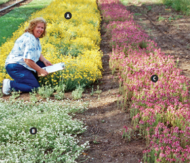
Figure 5-63 | Commercially-grown native seed grow-out fields
A variety of species can be propagated for seed. In this photograph, small seedlots of forbs are being propagated at the USFS J. Herbert Stone Nursery in southern Oregon. The beds in the upper left (A) are western buttercup (Ranunculus occidentalis); lower left (B) is fragrant popcorn flower (Plagiobothrys figuratus), and the bed on the right (C) is elegant calico flower (Downingia elegans). Photo credit: David Steinfeld
Introduction
Many revegetation projects require large quantities of grass or forb source-identified seed. The most common approach to obtaining such quantities is to establish seed increase fields in nurseries or agronomic environments. Here, plants can be irrigated, fertilized, and cultured specifically to produce a large amount of seed adequate for large-scale seedings (Figure 5-63). Usually the seeds are produced by the end of the first or second year of production. The field-grown seed can then be direct sown in restoration projects, or stored in a warehouse in anticipation of future needs.
Considering the costs and amounts of seeds that can be obtained from wild seed collection, propagating grass and forb seed is very efficient. For example, mountain brome (Bromus carinatus) can require 8 pounds of wild seed to sow a 1-acre seed field. At the end of the first year, the seed collected from these fields can average 800 pounds, a hundred-fold increase. For many grass species grown in production beds for two years, the yield is at least 50 pounds of seed produced for every pound of wild seed collected and sown. In some cases, 100 pounds are collected per pound of wild seed sown. The efficiency of large-scale seed increase will vary with species, quality of starter seed, grower, and geographic region. This section outlines the steps required for developing and administering seed increase contracts.
Develop Timeline
Seed production varies by species and weather condition during production, but typically it takes three years to obtain the desired quantity of seed. This involves one year to obtain seed from wild collections and at least two years for seed production (Figure 5-64). The series of steps or tasks to obtain seed are described in detail in this section:
- Determine seed needs
- Obtain starter seed
- Develop and award contract
- Administer contract
- Store seed
It is helpful to determine a rough approximation of the quantity of needed seed for each species early during the planning phase. Seed quantities will be refined as planning progresses, but because of the amount of time that is takes for wild seed collection and seed production, it is important to make an estimate early in the planning stages. Developing and awarding wild seed collection contracts is the first task and this can take several months (Section 5.3.4). To avoid missing the seed collection window, these contracts are typically awarded by early spring for most species, otherwise an additional January for spring sowing. It is important to prepare and award seed increase contracts well in advance of sowing to allow the seed producer enough time to prepare and sow their fields. Specific sowing dates will differ for each seed producer because of differences in geographic location, climate, or experience. If growers are certifying the seed crop through a state program, requirements that the fields are isolated from other fields of different accessions of the same species may involve additional planning and preparation time as well. It is beneficial to contact the potential growers prior to award of contracts to find out when sowing and first harvests are expected. Once wild seed has been collected, cleaned, and tested, it is delivered to the seed producers.
Seed increase contracts could cover a span of at least two years to account for the possibility of a low first year harvest. Seed harvests occur during the summer and seed cleaning in the fall of each year. Once seed has been cleaned, the grower submits a sample from each seedlot to a seed laboratory for seed quality testing. Seed is placed into climate controlled storage until it is needed. If the seed that is harvested in the summer is needed for immediate fall sowing it is good practice for the designer to communicate with the grower to ensure that those seedlots are prioritized for processing and testing.
Determine Seed Needs for Seed Production
Determining total seed quantities for a revegetation project is most effectively done as soon in the planning process as is feasible because wild seed collection contracts and seed propagation contracts are based on these figures. At this point, only a rough approximation of seed needs is necessary.
Calculating the needed quantities of seed is performed for every species that will be used on a revegetation project. This involves estimations since specific seed data is unavailable at this point in planning. The information that necessary to make these calculations includes an estimate of the following factors:
- Pure live seeds per pound
- Field survival
- Target seedling density
- Target species composition
- Area to seed
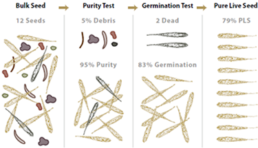
Figure 5-65 | Pure live seed
Pure live seed (PLS) is the percent of the bulk seed weight that is composed of viable seed. In this example, 95 percent of the bulk weight is composed of seed and, of this seed, 83 percent was found to germinate from seed tests. Multiplying percent purity by percent germination and dividing by 100 gives percent pure live seed.
Pure Live Seeds per Pound (PLS/lb)—The quality of wild collected seedlots can vary greatly. One method to assess seed quality is to calculate percent pure live seed (PLS). This value represents the percent of the gross seed weight composed of viable seeds. For example, if a seed producer did not clean the harvested seed of a seedlot very thoroughly, the PLS would be low because there would be a lot of additional weight associated with non-seed debris. Seedlots that were cleaned well, however, would have a higher PLS because the debris weight would have been removed. Seedlots that have higher germination rates also have higher PLS. These two factors, percent purity and percent germination, when multiplied together and divided by 100, give the PLS of a seedlot. The concept of PLS is illustration Figure 5-65. In this example, purity of a grass seedlot is 95 percent and germination is 83 percent, which result in a PLS of 79 percent.
Another example of calculating PLS/lb is shown in Figure 5-66 for western pearly everlasting (Anaphalis margaritacea). For this seedlot, the estimated purity is 60 percent, which indicates that more than half of the gross weight of seed is actually viable seed and the remaining part is either debris or non-viable seed. Multiplying this value by the percent of seeds per pound and by the percent of germination yields the number of viable seeds per pound. In this example, the number of seeds in a pound of a western pearly everlasting seedlot is tested at 8,000,000. Multiplied by 60 percent purity and 85 percent germination gives a value of approximately 4,080,000 PLS per pound of bulk seed. This value can be used in sowing calculations, as shown in the example. Note that for each additional seedlot in a mix, similar calculations will have to be made. Estimates for purity, germination, and seeds per pound can be obtained from Table 5-15, seed inventories, or seed extractory managers.
Field Survival—Field survival factors account for the viable seeds that, for one reason or another, do not grow into plants within the year after seeding. It accounts for viable seeds that did not germinate because of the harsh site conditions or did germinate but could not survive the site. The field survival factor reflects the harshness of the site. For example, seeds that are sown under mulch on a moist, cool site will survive better than seeds sown on hot, dry sites without mulch, in which case the survival factor would be much lower. Only an estimate of field survival can be made at this time based on a general understanding of the site (Section 5.4.1, see Determine Sowing Rates). Choosing a survival factor between 3 percent (poor site conditions and poor seeding practices) and 25 percent (good site conditions and practices) is likely sufficient for this estimate. In Figure 5-66, the field survival was set very low because of the harshness of the site.
Target Seedling Density—The target first-year density indicates the number of plants per square foot that is desired one year after sowing. This is the target number of seedlings for all species sown in a 1 square-foot area. Seedling densities range from a target of less than one plant per square foot for shrub and tree species to 10 to 25 seedlings per square foot for grasses and forbs (Section 5.4.1, see Determine Sowing Rates).
Target Species Composition—The target composition defines the percent of established plants that are made up of each sown species. For example, if three species are sown, the target composition of plants might be 50 percent species A, 35 percent species B, and 15 percent species C. The target species composition is developed from reviewing field surveys of disturbed and undisturbed reference sites. In the example shown in Figure 5-66, only 10 percent of the composition of plants is targeted to be pearly everlasting.
Table 5-15 | Seed increase reference table for native grass species
This table show the approximate maximum cleaned seed needed for a seed producer to produce a 1-acre production field. It also shows average first and second year yields and germination and purity standards for commonly produced species in the Pacific Northwest US.
|
Species |
Sowing rates (lbs of clean seed to sow per acre) |
Average first year yields (lbs/ac) |
Average second year yields (lbs/ac) |
Average seeds per pound |
Average germination/ purity of harvested seeds |
Bluebunch Wheatgrass
Pseudoroegneria spicata |
8 |
200 |
300 |
140,000 |
75/95 |
| Blue Wildrye Elymus glaucus |
6 |
450 |
200 |
110,000 |
65/96 |
| Bottlebrush Squirrel- tail Elymus elymoides |
6 |
0 |
125 |
110,000 |
75/90 |
| California Oatgrass Danthonia californica |
8 |
25 |
250 |
125,000 |
75/90 |
| Basin Wildrye Leymus cinereus |
8 |
25 |
160 |
130,000 |
75/95 |
| Idaho Fescue Festuca idahoensis |
4 |
50 |
400 |
450,000 |
75/90 |
| Indian Ricegrass Oryzopsis hymenoides |
6 |
0 |
200 |
120,000 |
80/85 |
Lemmon’s Needlegrass
Achnatherum lemmonii |
8 |
150 |
750 |
150,000 |
50/95 |
| Mountain Brome Bromus carinatus |
10 |
800 |
600 |
70,000 |
85/90 |
| Needle and Thread Hesperostipa comata |
6 |
0 |
150 |
100,000 |
50/95 |
| Pinegrass Calamagrostis rubescens |
2 |
0 |
130 |
2,500,000 |
75/75 |
| Prairie Junegrass Koeleria macrantha |
2 |
150 |
500 |
2,315,000 |
80/97 |
| Sandberg Bluegrass Poa secunda |
3 |
300 |
600 |
1,314,000 |
75/97 |
| Slender Hairgrass Deschampsia elongata |
3 |
600 |
350 |
2,000,000 |
80/95 |
Thurber’s Needlegrass
Achnatherum thurberianum |
5 |
0 |
150 |
225,000 |
50/95 |
| Tufted Hairgrass Deschampsia caespitosa |
2 |
110 |
510 |
2,500,000 |
75/90 |
Western Needlegrass
Achnatherum occidentale |
5 |
100 |
190 |
275,000 |
50/95 |
| Common Yarrow Achillea millefolium |
2 |
165 |
165 |
3,000,000 |
85/98 |
Western Pearly Everlasting
Anaphalis margaritacea |
1 |
50 |
50 |
8,000,000 |
60/85 |
Area to Seed—This is the total area that is planned to be revegetated from seed based on the estimated acres presented in the preliminary road plans.
In the example shown in Figure 5-66, the seed needs for pearly everlasting is calculated to be approximately 22 pounds for the entire 25 acre project. This might seem like a very low amount of seed for a project of this size, but it reflects the high live seeds per pound for this species.
Obtain Starter Seed
Once the seed needs for a project are determined, the next step is to obtain starter seed to supply to the seed producer. Seed furnished to the seed producer is best when it is of high quality and tested for purity, germination/viability (Tetrazoleum or TZ), seeds per pound, and noxious weed content (Section 5.3.1, see Clean and Test Seeds). Seedlots with high weed content will produce weedy fields. It is very expensive to weed non-target species out of seed production fields or clean non-target seeds from harvested seedlots, so it is important to give seed producers only the highest quality starter seed. It is worth the investment, and almost always essential, to send wild seed collections to a seed extractory to be cleaned prior to sending to the seed producer. Section 5.3.1 (see Determine Wild Seed Needs for Seed Production) describes how to determine how much wild seed to collect for starting seed production crops.
For some projects, it may be difficult to collect enough wild seed in a single year to establish a seed increase field. In these cases, the seed may be stored and additional collections made over time until a sufficient quantity of seed is obtained for field establishment. The seed may also be first sown in small plugs (1 to 2 cubic inch size) at a nursery, and then transplanted into a seed production field at low densities (<1 seedling per foot). This will reduce the overall amount of seed needed to establish a seedbed, and seed production from these beds is often greater because plants are evenly spaced.
Develop Contract
The seed production contract can state for each seedlot being grown:
- Seedlot ID
- Years each seedlot will be in production
- Minimum annual seed yields for each seedlot
- Minimum purity and germination rates
Minimum annual seed yields and average germination and purity rates can be obtained from Table 5-15 and Table 5-16. For species and regions not represented here, this information can be obtained from agencies such as the NRCS, private growers, and the Native Seed Network (www.nativeseednetwork.org). The years that a seedlot will be in production will vary by species and lead time (Section 5.3.4, see Develop Timeline).
Additionally, the seed production contract can address what is required or expected of the contractor in respect to the following criteria:
- Seed production experience
- Timelines
- History of production field
- Isolation distance from fields planted with other seedlots of the same species (to avoid cross-pollination and maintain genetic integrity of the seed crop)
- Irrigation system
- Culturing practices
- Control measures for non-target species
- Seed harvest methods
- Seed cleaning, packaging, and labeling
- Seed testing
The response to these criteria becomes the basis for selection of contractors.
Seed Production Experience—Native seed production is a specialized form of agriculture requiring highly customized growing strategies and equipment. While many seed producers have transitioned in seed production easily, it still usually takes several years of experience with any given species to understand how to efficiently grow native seed on a commercial scale. Many seed producers who have moved into growing native seed have previous experience growing vegetable or commercial pasture and turf grass seed. These seed producers bring great experience and perspective to the native seed industry. Seed producers, who have had little experience growing native seed often start small with easier species (e.g., many workhorse species) to gain experience. It is important to know the capability of each seed producer and make frequent site visits. Those with a long history of good seed production can be contracted for species that are more difficult or have not been grown before. It is good to request production records, as well as seed tests and to include species, seed yields, seed quality, and clients served by the producer.
Table 5-16 | Seed increase reference table for native forb species
This table shows the approximate maximum cleaned seed needed for a seed producer to establish a 0.1-acre production field for key forb species in the Pacific Northwest US. Also listed is the timing and method of field establishment, field longevity, and average seed yields per 0.1 acre plot for years 1-3. A complete forb seed increase table can be obtained in the Native Revegetation Resource Library.
|
Species |
Seed quantity needed to plant 0.1 ac plot (ounces) |
Timing of planting |
Planting method* |
Field longevity (years) |
Production yield per
0.1 acre plot (lbs/year; years 1, 2 and 3) |
| Western yarrow Achillea millefolium |
3-4 |
Summer |
DS |
3-4 |
5-15 |
30 |
30 |
| Nettlelead giant hyssop Agastache urticifolia |
5-6 |
Fall |
Tubes/DS |
2-5 |
2-5 |
5-10 |
10+ |
| Bigflower Agoseris Agoseris graniflora |
5-6 |
Spring/Fall |
Tubes/DS |
2-3 |
40 |
40-80 |
— |
| Basin big sagebrush artemisia tridentata |
3-4 |
Fall |
Tubes |
10-15 |
0 |
10-20 |
20-40 |
| Showy milkweed Asclepia speciosa |
6-8 |
Spring/Fall |
Tubes/DS |
3 |
0 |
20 |
40 |
| Canadian milkvetch Astragalus canadensis |
5-7 |
Spring/Fall |
Tubes/DS |
3-4 |
0 |
20-40 |
40+ |
| Basalt milkvetch Astragalus filipes |
5-7 |
Spring/Fal |
Tubes/DS |
3-4 |
0 |
20-40 |
40+ |
| Douglas' Dustymaiden Chaenactis douglasii |
5-6 |
Spring/Fall |
Tubes/DS |
1-2 |
20-30 |
50 |
— |
| Clarkia Clarkia spp. |
3-4 |
Spring/Fall |
DS |
1 |
30 |
— |
— |
| Yellow Spiderflower Cleome lutea |
3-4 |
Spring/Fall |
DS |
1 |
50-60+ |
— |
— |
| Grand collomia Collomia grandiflora |
3-4 |
Fall |
DS |
1 |
15+ |
— |
— |
| Blue Muontain prairie clover Dalea ornata |
5-7 |
Spring |
Tubes |
4-5 |
0 |
20-40 |
60+ |
| Threadleaf Fleabane Erigeron filifolius |
3-5 |
Spring/Fall |
Tubes/DS |
3 |
0-5 |
15+ |
15+ |
| Shaggy Fleabane Erigeron pumilus |
3-5 |
Spring/Fall |
Tubes/DS |
3 |
0-5 |
15+ |
15+ |
| Aspen Fleabane Erigeron speciosus |
3-5 |
Spring/Fall |
Tubes |
3-4 |
0-15 |
30-100 |
100+ |
Seed Production Timelines—Seed producers are located throughout the United States that encompass a broad range of climates affecting when seeds are sown and harvested. It is important to know the general growing schedule of each seed producer in your region to determine when to supply starter seed to the seed producer and when the first shipment of harvested seed can be expected. Some seed producers wait until spring to sow seed crops, in which case the seed harvest in the first year may be significantly reduced. Depending on the climate and species, seed harvests can occur as early as May to as late as August. It is important to specify a date in the contract when seed will be delivered, especially if the seed will be used in the same year it is harvested.
History of Production Fields—Every field will have some amount of residual seeds from previous crops that will germinate along with the starter seed supplied by the designer. Knowing the history of the fields during the planning stages helps determine whether these non-crop plants pose a problem for seed production. Noxious weeds or undesirable non-native species are a concern, but many of these species can be rogued out of the seed beds prior to harvesting. Of more concern are fields where the same native species, but from a different seed source (especially from a different climate), were grown. For example, a field is being prepared for sowing California fescue (Festuca californica) from a seed source in the Blue Mountains of northeastern Oregon. The field had previously grown California fescue from a seedlot collected west of the Cascades. Because seed from the previous fescue crop would germinate in the same bed, the resulting crop would include both seedlots. Because the plants from these seedlots would appear almost identical, it would be impossible to weed out the plants that came from the previous crop. Even species in the same genera are difficult to distinguish by untrained weeders and cannot be weeded out of beds.
It is good practice to evaluate fields that previously produced seed from the same or similar appearing species for the risk of seed contamination from previous seed crops. Seed producers can take measures to reduce contamination risks. These include growing non-seed crops for several years between seed crops, rotating between grass and forb seed production (forb seed is easy to discern from grass seed), and fumigating between seed crops. These strategies can be discussed with the seed producers. State seed certification guidelines and standards are becoming increasingly available for many native species.
Location of Other Seedlots—Equally important to the history of seed production fields is the location of nearby seed crops of the same species. If seedlots of the same species are being grown close by, the risk of cross-pollination between crops increases and the genetic integrity of the proposed seed crop could be compromised. There can even be cross-pollination between similar species. For example, blue wildrye (Elymus glaucus), bottlebrush squirreltail (Elymus elymoides), and bluebunch wheatgrass (Pseudoroegneria spicata) are known to cross-pollinate. Local botanists or geneticists can be consulted about which species can potentially cross breed. Seed crops that can cross-pollinate can also be separated by a minimum isolation distance. Under most circumstances, the isolation distances are in accordance with State Certification Standards (certified class). These standards can be found at the AOSCA website or the departments of agriculture for each state. State seed certification specialists can often provide recommendations for species of interest that lack official isolation standards.
Irrigation System—Many native species are to be grown under irrigation to meet the quantities of seed specified in the contract. Seed producers that have minimal or no irrigation capacity are often unlikely to meet seed production requirements and time frames. It is helpful when growers lacking irrigation systems are only offered those species that do not require irrigation.
Culturing Practices—A review of culturing practices, which include irrigation, fertilization, disease, and insect control, can be done to determine whether they are appropriate for the production of the species being grown. Culturing practices are often written up in propagation protocols that can be found on the Native Plant Network. Many university nurseries and NRCS Plant Material Centers also publish propagation protocols and useful plant guides and fact sheets.
Control Measures for Non-Target Species—Specific attention can be given to how weeds and other non-crop species will be controlled. Typical measures include the use of herbicides prior to sowing and after the crop has been established, and manual weeding of non-target species. The most important period of weed control is just prior to seed harvest because of the importance of eliminating potential non-target seed before harvesting occurs.
Seed Harvest Methods—Most seed harvests are conducted with specialized equipment that detaches seed from the stock, separates it from plant and soil debris, and collects it into storage containers (Figure 5-67). It is important to know the seed harvesting equipment that will be used for each species and how it will be cleaned between individual crops to prevent the possibility of contamination among seedlots.
It is best to collect species with indeterminate inflorescences (seeds that ripen on the seed stock all summer long) more than once in the summer. This repeated harvest can be done manually or with specialized equipment such as motorized leaf blowers that are operated in reverse as vacuums. Periodic seed harvests of these species can be planned so that the full range of seed can be collected. The designer might anticipate higher financial costs for indeterminate species given the extra harvest efforts. The seed producer can address how these species will be harvested to obtain the maximum seed yield.
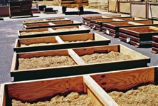
Figure 5-68 | Seed harvesting and drying
Seed is harvested and dried prior to cleaning and storage. This photograph shows a recently harvested seedlot in drying trays prior to being set on a forced air drier. Seed ID tags are attached to the side of each seed drying bin. Photo credit: David Steinfeld
Seed Cleaning, Packaging, and Labeling—After seed is harvested, it can be dried and further cleaned. Seeds are air dried (Figure 5-68). Seeds are then extracted and cleaned. Awns and flower parts are removed, and then dirt, stems, and other debris are separated from the bulk seed. Understanding the cleaning operation is important because viable seeds can be damaged or discarded during this process.
For typical warehouse storage, dry cleaned seed is best packaged in “breathable” woven poly bags at uniform weights Industry standards are 25- or 50-pound bags. It is good practice to clearly identify bags of seed with an affixed tag stating the species name (scientific and common), seedlot identification/source code, percent germination, percent purity (including other crop seed, weed seed, and noxious weeds), date of seed test, and seed producer’s name. Additional certification tags or labeling information may be requested, such as project name, National Forest or BLM office, or seed owner name.
Seed Testing and Acceptance—The contract could state the minimum acceptable standards for each species and seedlot. Acceptance and payment can be based on meeting the standards set for the following:
- Germination
- Purity
- Weeds
- Moisture content
Seed testing is typically the responsibility of the contract grower. Seed samples used for testing and contract performance could be taken by a certification agency representative or a contract inspector who is trained and certified in proper seed sampling methodologies. Samples could be tested by a state certified seed laboratory (Section 5.3.1, see Clean and Test Seeds) Seed test results can be identified by the seed source identification and task order number. It is good practice to have the project’s owner agency confirm that test results are satisfactory before final acceptance of the seed is made.
Establishing minimum germination and purity rates can be based on averages obtained from commonly produced species shown in Table 5-15 and Table 5-16 and other available sources, or through discussion with seed extractory managers. The contract can address what actions the contract-grower can take to increase either germination or purity if these rates fall below the standards. Lower purity rates can be accepted if seed will be used in a hydroseeder (Section 5.4.2). A TZ test may be made in lieu of a germination test for a seed viability test depending on time constraints and species involved. Once any necessary State Noxious Weed examinations are performed, if any of these species are present, then the seedlot can either be rejected or re-cleaned. The seed moisture test can also be conducted to confirm that the seed does not exceed 10 percent moisture.
Administer Contract
Seed producers maintain adequate records to allow the Government to monitor contract progress. Records include information and dates of field preparation, seed sowing, field treatments, fertilization, seed harvest, cleaning, storage, seed yields, and any other activity relating to seed production. It is a good practice to make contact either by phone or by visiting the seed producers two to three times a year to go over the progress of the contract. The best time of year for field visits is just prior to or during seed harvest (Figure 5-69). A visit or phone contact in fall is important to discuss the potential of keeping seedlots additional years. Visiting in the late summer or fall is also a good time to observe the seed extraction and cleaning processes. Unless it is stated in the contract, seed production fields are likely to be plowed under once the seed orders have been met. If seed in excess to the order is produced, contracts often specify that the Government has first right of refusal for the additional amount, often at a reduced or negotiated price.
During these visits, it is important to note the condition of the seedlots and how they are being identified throughout the production phase and subsequent processes. Are there clear labels stating the seedlot identification in the field, during drying, extraction, and storage? Are seed harvest and extraction equipment being thoroughly cleaned between seedlots or are there remnant seeds remaining in the equipment that can contaminate the next seedlot being processed? Note the condition of the fields prior to seed harvest. Are the fields weedy and will there be a final weeding before harvest? Are seeds being handled with care or are they roughly handled? These same questions and practices are also used during the state seed certification process.
A good working relationship with the seed producer is helpful in meeting the overall seed increase objectives. Some factors, such as weather, are beyond the control of seed producers, and in some years seed harvests will fall short of the minimum amounts stated in the contract. Good communications with the seed producer will allow designers to learn of crop failures or fall down in orders as soon as they occur so that alternative measures can be taken. An inventory of the number of acres in each seedlot and the condition of the crop can be supplied by the contract grower upon request.
Seed Storage
Seeds can remain viable in properly controlled storage for many years after harvest. How well seeds keep depends on the moisture content of the seed, the quality of the seed being stored, the storage conditions (temperature and humidity) and presence of damaging agents such as rodents, insects, or mold). Seeds typically store poorly when seed quality is low, or seed moisture content is above 10 percent. Fluctuating temperatures will also shorten seed longevity. If seedlots are stored for more than a couple of years, it is important to periodically test the seed for germination.
Granary Storage—Most seedlots are stored for short periods before they are used on projects (usually less than five years). For this reason, granary storage is the most common and economical form of seed storage, especially for larger quantities of grass and forb seed. Granary storage units are enclosed rooms sheltered from rainfall and temperature extremes. Storage temperatures are ideally near 10° C, with humidity less than 20 percent. Storage containers are typically insulated and protected from rodents and insects. While some seedlots can be stored for long periods, it is good practice to use low quality seed first because it is more likely that this seed will lose viability in storage compared to high quality seed.
Freezer or Refrigerator Storage—Freezer storage (~9° C) is usually reserved for seedlots that will be stored for many years. Conifer and shrub seeds, as well as small forb and grass wild seed collections, are usually stored under these conditions. Berries, however, cannot be frozen, as the moisture content may be too high and could damage the seed embryo. Instead, berries are best stored in refrigerators at temperatures ranging from 1 to 3 degrees C. Seed of some species, such as maples, also need to be stored in refrigerated conditions but may require special pre-treatments, even for short-term storage.
Seed extractory managers are excellent sources of information for more detailed guidance on proper storage conditions for particular species.
5.3.5 NURSERY CUTTING PRODUCTION
Introduction
Obtaining cutting materials in the wild for restoration and bioengineering applications can be a difficult and expensive task, especially if populations of parent material are small or access is limited. Native plant nurseries can be an alternative source for a variety of woody cuttings. Understanding how nurseries establish and manage “stooling beds” can be a great help to designers and project engineers.
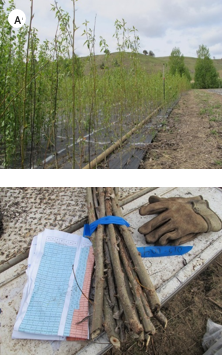 Figure 5-70 | Stooling beds produce cuttings
Stooling beds (A) are an efficient way of ensuring that a ready supply of hardwood cuttings of the proper species and source are available (B).
Photo credit: Matt Horning, USFS
What are Stooling Beds?
“Mother plants” are established in nurseries for the sole purpose of providing a ready source of cuttings. Stooling beds are hedge-like rows of mother plants that are established in bareroot nurseries or in vacant fields (Figure 5-70A). Stooling beds are more commonly referred to as “cutting beds”.
Stooling beds take advantage of the ability of many broadleaved woody plants to sprout profusely from the base after being cut off just above the root crown (i.e., coppiced). Plants remain in the juvenile state, which means they have a higher tendency to sprout and produce roots. Once stooling beds are established, annual cutting ensures that juvenility can be prolonged for multiple years. After repeated harvests, stooling beds will lose productivity after a few years. However, new beds can be created using cuttings from declining beds such that the unique genotypes in a given bed can be preserved for many years.
Stooling beds allow for the efficient collection of dormant hardwood cuttings during winter when it may be difficult or impossible to make field collections (Figure 5-70B). Because the beds are located in agronomic settings, they can be irrigated and cultured; processing and storing the cuttings is also much more efficient and cost-effective. Cuttings from stooling beds have several advantages over wild collected cuttings.
Maintaining Genetic and Sexual Diversity—It is much easier to correctly identify different plant species and ecotypes from labeled stooling beds as compared to wild collections. For example, willows often grow together along streams and can be difficult to identify during the winter dormant season. Stooling beds offer the ability to produce a large number of cuttings of unique species or ecotypes quickly and easily.
Many government nurseries have established stooling beds of the species and ecotypes that are adapted to local seed zones areas and can thus be a potential source starter material for private growers or out-planting materials for designers. Private native plant nurseries also establish stooling beds of desirable species for their local areas, and several specialize in riparian and wetland species. For specific revegetation projects, however, the odds of a nursery having existing stooling beds of the proper species and local ecotype are low. Therefore, collecting cuttings and establishing stooling beds is best done early in the planning process so a good supply of cuttings will be available when needed.
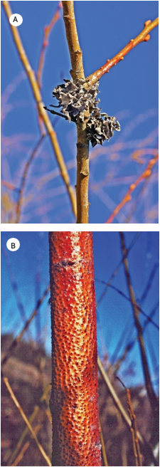 Figure 5-71 | Stooling beds are managed production facilities
Stooling beds can be cultured to prevent the occurrence of insect galls (A) and fungus cankers, such as Cytospora spp. (B).
Photo credit: Thomas D. Landis
Some plants, such as willows and cottonwoods, are either male or female, which is an important consideration in restoration (Landis et al 2003). If a balanced mixture of male and female plants is not collected from the project site, the resultant stooling beds will not produce both male and female cuttings. When working with dioecious plants, the sexual identity of potential mother plants is best determined prior to collection (Section 5.3.2). It is essential that a restored population is contains a mix of female and male plants to ensure the established population’s capacity for sexual reproduction.
Producing Healthy and Vigorous Cuttings—One of the most practical advantages of establishing stooling beds is that the cuttings from the beds are often healthier and more vigorous than those collected from the project site. Wild stands of willows are host to many insects and fungal pests, such as galls and cankers (Figure 5-71). They are also subject to animal browsing. These factors can significantly lower the quality of wild-collected cuttings. Cuttings from the stooling beds can root at over 99 percent, thereby lowering establishment costs and keeping the project on schedule (Dumroese et al 1998).
Reducing Costs—It might seem that collecting cuttings in the wild would be the least expensive means of obtaining cutting materials. This is not necessarily the case. Inefficiencies of driving to remote locations, pulling cutting materials to roadways, using make-shift cutting practices, and working under severe winter conditions all add up to high costs per cutting.
Select Species Suitable for Stooling Beds
Poplars, cottonwoods, and willows are the species most often used in stooling beds. However, all species of the willow family are not necessarily good candidates for stooling beds. Some species have growth characteristics that reduce their potential. For example, trials at the Colorado State Forest Service Nursery in Fort Collins have shown that narrowleaf cottonwood (Populus angustifolia) and narrowleaf willow (Salix exigua) do not “stool” well and are best propagated by other methods (Grubb 2007).
There is great potential for using other woody species that have the propensity to sprout and form roots easily. For example, redosier dogwood (Cornus sericea) is commonly grown in stooling blocks and used as a source of cuttings for restoration sites. Outplanting success is higher than with wild cuttings collected on the project site and has ranged from 50 to 90 percent (Hoag 2007). In North Dakota, twinberry honeysuckle (Lonicera involucrata) is being investigated (Morgenson 2007). Native species that root easily from hardwood cuttings have the potential to be grown in stooling beds to generate cuttings. Species that have inherent deep seed dormancy characteristics, such as snowberry, honeysuckle, elderberry, and some species of currants, could be more easily propagated in the nursery using stooling beds than sowing seeds to produce seedlings. Species that have consistently low seed viability, such as mock orange and ninebark (Physocarpus spp.), may also be produced more economically in stooling beds.
The Plant Materials Centers of the NRCS identified the potential of a wide variety of woody native plants that would be suitable for stooling beds (Table 5-17). For example, Crowder and Darris (1999) discuss which plants are suitable in the Pacific Northwest and provide a wealth of information on the installation and culture of stooling beds.
Darris (2002) performed extensive greenhouse and field trials to test the potential of several woody plants for live stake applications. Common snowberry (Symphoricarpos albus), salmon- berry (Rubus spectabilis), Pacific ninebark (Physocarpus capitatus), and twinberry honeysuckle (Lonicera involucrata) have proven to be effective as live stakes for soil bioengineering in the Pacific Northwest. Notably, several have proven to be superior to willow on some sites, such as salmonberry in wet, shaded environments, and snowberry on drier, exposed locations.
Table 5-17 | Native woody plants of the Pacific Northwest with potential for propagation in stooling beds
|
Species |
Rooting ability |
Growth rate |
Establishment success
(1=Poor, 5=Good) |
| Coyotebursh Baccharis pilularis |
Fair to Good |
Moderate |
3 |
| Redosier dogwood Cornus sericea |
Good |
Fast |
3 |
| Indian plum Oemleria cerasiformis |
Poor to Good |
Moderate |
1 |
| Pacific ninebark Physocarpus capitatus |
Good to Very Good |
Moderate to Fast |
4 |
| Lews’ mock orange Philadelphus lewisii |
Fair |
Moderate |
1 |
| Black cottonwood Populus trichocarpa |
Fair to Very Good |
Very Fast |
3 |
| Woods’ rose Rosa woodsii |
Poor to Fair |
Moderate to Fast |
1 |
| Peachleaf willow Salix amygdaloides |
Excellent |
Very Fast |
5 |
| Narrowleaf willow Salix exigua |
Very Good |
Fast |
4 |
| Arroyo willow Salix lasiolepis |
Excellent |
Very Fast |
5 |
| Scouler’s willow Salix scouleriana |
Good to Very Good |
Very Fast |
4 |
| Rose spirea Spiraea douglasii |
Very Good |
Fast |
4 |
| Common snowberry Symphoricarpos albus |
Very Good |
Fast |
4 |
Modified from Crowder and Darris (1999)
Select the Type of Cutting Material
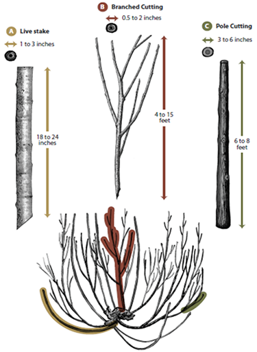 Figure 5-72 | Different cutting types serve unique purposes in revegetation
Several types of hardwood cuttings can be obtained from stooling beds, including cuttings for propagation at the nursery or live stakes and branched cuttings for restoration projects. Note that larger plant materials may require extra time to produce.
Several different types of cutting materials can be collected from stooling beds. Nurseries can use small propagation cuttings (perhaps short as one inch) to start their own bareroot or container plants. Stooling beds can also provide several types of unrooted cuttings used in restoration (Figure 5-72).
LiveStakes—Live stakes are so named because, in addition to providing stability on restoration sites, they are expected to root and sprout after installation (Section 5.4.3, see Live Stakes). Because they are often pounded into the ground, live stakes are cut from relatively straight sections of second- or third-year wood. Live stakes are typically 18 to 24 inches in length and from 1 to 3 inches in diameter (Figure 5-72A). Depending on the plant species, it can take two to four years for a stooling bed to produce large enough branches for live stakes. Some of the smaller willow species will never grow large enough.
Whips—Whips (not shown in Figure 5-72) are similar to live stakes except they have a much smaller diameter of less than an inch. Whips can be planted by “sticking” them directly in the ground. Because of their small diameter no tools are necessary to install them.
BranchedCuttings—Bioengineering practices, such as live fascines, waddles, vertical bundles, brush layers, and pole drains (Section 5.4.3) require a large number of branched hardwood cuttings (Hoag and Landis 2001). The size of this material ranges from 0.5 to 2 inches in stem diameter and 4 to 15 feet in length (Figure 5-72B). Stooling beds may take two or more years to produce significant numbers of harvestable branched cuttings.
Pole Cuttings—Pole cuttings (Figure 5-72C) are large diameter (3- to 6-inch) main stems that have all side branches with the top 1 to 2 feet of stem removed. They are used in restoration projects where stability is a main concern. Because of the large size of the plant material necessary for pole cuttings, nursery stooling beds are ideal. Larger trees, such as cottonwoods and tree-sized willows (e.g., Goodding’s willow [Salix goodding]), have primarily been used for pole cuttings. Other large woody plants with the potential to sprout may also prove to be viable material (Dreesen and Harrington 1997).
Develop Timeline
Obtaining cutting materials from established stooling beds takes between one and five years, depending on the type of material. A minimum of one year is necessary to produce branched cuttings; two to four years to produce live stakes; and pole cutting may require more than four years (Figure 5-73). During the planning stages of the revegetation project is when the number, type, and species of cuttings needed for the project is determined. Procedures for making these calculations are outlined in Section 5.3.2 (see Determine Cutting Needs). Nurseries or government facilities that specialize in stooling bed production can be contacted to see if they will establish stooling beds for the project. Managers of these facilities can provide information regarding costs and the time frame for meeting the orders. While some cutting materials will be produced in the first year, full production of stooling beds does not occur until several years after installation.
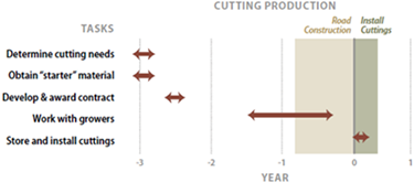 Figure 5-73 | Plan early to ensure cuttings are ready for a project
Obtaining cutting materials from stooling beds can take up to four years, depending on the type of material requested. Branched cuttings can be obtained from stooling beds after the first growing season, while live stakes can take from two to four years. Pole cuttings can take even longer. The following is a timeline for producing branched cuttings and some smaller live stakes. Add several years for large stakes and some poles.
Most stooling beds are started from cuttings taken from the wild. The sources of starter material can be located in the field during the summer or fall prior to installation of the beds. The sexual identity of dioecious plants can also be determined during the appropriate season prior to collection. This is not a simple task and can require the expertise of a skilled botanist or native plant specialist. Section 5.3.2 (see Locate Cutting Areas) provides an outline of the steps necessary to obtain starter material. The nursery managers will provide information regarding the number of feet of starter material (or number of cuttings), the quality of the wild collections (age, size, condition), and packaging and shipping methods necessary to meet the order. Wild cuttings are collected when the donor plants are dormant (i.e., no leaves present). Depending on the climate of the site, collections can begin in mid to late fall and end from late winter to mid-spring. Wild cuttings are usually sent immediately to the nursery where they are prepared for installing in stooling beds. Most stooling beds are started directly from cuttings that are stuck in the spring. Cuttings root quickly in the spring and, with irrigation and fertilization, grow into large plants by the end of the summer. The following winter, the beds are ready for harvest. Because stooling beds are relatively uniform, the material can be harvested and processed in a production-oriented manner. Cutting materials are cut to specifications and stored in either freezer or cold storage facilities until delivery is requested.
The development of stooling beds is a long-term investment, and they often take several years to fully establish. However, they can remain productive for many years depending on species, ecotype, nursery cultural practices, and pest management. For cottonwoods, stooling beds typically remain productive for four to eight years, after which vigor and productivity start to decline. Importantly, cuttings from declining beds can be used to create new beds ensuring the preservation of individual genotypes and this eliminates the need to return to the original source location in the field. However, other nurseries have maintained stooling beds of willow and cottonwood for 12 to 15 years without decreases in vigor. Cytospora canker, caused by fungi of the genus Cytospora spp. (Figure 5-72B), is a particularly serious pest of all Salicaceae and, because it is transmitted and thrives in wounded stem tissue, can ruin a productive stooling bed. The productivity and longevity of a stooling bed are a direct function of the amount of care given. Because stooling beds are an investment with long-term payoffs, finding local partners (watershed councils, federal, state, and county land managers) who can utilize these beds after project needs are met can be a service to the local community.
5.3.6 NURSERY PLANT PRODUCTION
Introduction
Planting stock with established root systems is often optimal for certain species, or for use in restoration projects that occur on very harsh or disturbed sites. This may be accomplished by growing plants from seed or rooted cuttings in nursery beds or in containers in a greenhouse for a period of time ranging from several months to several years. Woody plants are critically important because they quickly provide vertical structure and aesthetic relief on roadside revegetation projects. When planted within areas seeded with grasses and forbs, trees and shrubs provide the essential matrix of a successful revegetation project. Direct seeding is rarely used to establish woody plants on restoration projects because they are often slow to germinate and take several years to become established. Depending on site characteristics, many sizes of nursery stock can be used. If large plants are used, their physical size and deep roots allow them to more quickly access soil moisture at deeper levels, and their expansive lateral root systems help stabilize soils while also reaching more surface moisture. On some harsh rocky sites, smaller plants may have better initial survival and are more likely to colonize the area. In addition to providing wind protection and shade to lower growing vegetation, trees and large shrubs provide habitat for insects, birds, and other animals and can greatly accelerate the development of a sustainable plant community.
Grasses and forbs establish quickly and easily from seeds, so they are less frequently grown in nurseries. However, nursery stock is warranted under certain circumstances including the following:
- Sufficient quantities of grass and forb seeds are rare or hard to collect;
- Increasing grass and forb seeds by seed growers is difficult or excessively expensive;
- Establishing grasses and forbs is difficult due to site conditions;
- Restoring threatened or sensitive species is a high priority;
- Using nursery stock is more effective in restoring wetlands;
- Installing nursery stock is the best and fastest way to achieve a desired plant composition;
- Aggressive weeds are a serious problem.
For the Designer
When investigating plant material sources, designers can enlist the assistance of plant geneticists to help determine if a given source is genetically appropriate for a certain project area.
This section outlines the steps needed to obtain quality seedlings, transplants, or rooted cuttings from native plant nurseries. Typically, it takes one to two years to grow nursery plants; therefore, it is helpful for the designer to develop growing contracts and establish timelines several years in advance.
Develop Timelines
Obtaining some nursery stocktypes can take a considerable amount of lead time and planning. Although most native plant nurseries carry a wide variety of species, it is unlikely they would have plants that are genetically suitable for a specific project. However, it is worth investigating the available sources for genetic appropriateness as this can save time and funding. The large nursery stocktypes that will survive and grow on challenging restoration sites typically require several years to produce (Figure 5-74). It is therefore often necessary to develop contracts that will ensure that the correct genetic material is being propagated and that the resulting plants are of the highest quality that will survive and grow when planted on the revegetation site.
A project’s plant needs are determined early in the revegetation planning stages, including the number of plants, types of species, and size of plants. From the list of species, seed sources or “starter” plant material sources are located from suppliers or collected in the wild. This can typically take at least a year. Several years before the construction site is ready for planting, a contract for growing plants is developed and awarded. Once awarded, seeds and “starter” plant materials are sent to a nursery so that sowing, transplanting, or rooting of cuttings can begin.
The growing time for large container stock can extend from one to two years, depending on the species. The nursery will take a final seedling inventory during the middle of the final growing season. At this time, a planting plan can be finalized. Road construction will be moving into its final stage and the planting plan can be tailored to specific on-site conditions. From start to finish the whole process, including lifting, storing, and transporting plant materials, can take two to three years.
Determine Plant Needs
Early in the planning stages, a general idea of plant needs is developed based on the desired future condition for each revegetation unit. The information needed to determine the quantities for each revegetation unit includes the following:
- Area to plant
- Species mix
- Survival potential
- Plant spacing (density)
Using calculations similar to those presented in Figure 5-75, an estimate of the number of seedlings to order from nurseries can be determined. Calculations can be performed for each revegetation unit, because species mix, plant spacing, and survival will change considerably between units.
Planting Area—Summarize the acreage of all planting areas within each revegetation unit.
Species Mix—Good survival and establishment of plants fundamentally rests on selecting the most appropriate species from locally adapted seed sources. Selecting the species mix for each revegetation unit can be based on an evaluation of disturbed and undisturbed reference site descriptions that includes an understanding of the site limiting factors that will affect plant survival.
Survival Potential—Survival potential is an estimate of the percentage of planted seedlings that will survive and become established. Many factors determine how well nursery-grown plants will survive after outplanting. Factors that can be controlled include the following:
- Selection of appropriate species and seed source for the site;
- Quality of nursery plants;
- Appropriate storage and transportation conditions;
- Care in stock handling and planting.
High rates of plant mortality are usually the result of an oversight or neglect of one or more of these factors. Projects with high plant mortality may indicate poor planning or implementation. However, aiming for 100 percent survival is often unreasonable because of the high associated costs. Most projects aim for a plant establishment rate of 85 to 90 percent, but consider planning for 75 percent. It is more economical to plan for some small extra plants and care now to insure adequate survival up front, than to be faced with a new plan for additional plant material growing and planting at a future date.
There are many reasons why plants may not survive on a project site and one of the most important considerations to address is seed source and genetic appropriateness. If genetic considerations are not addressed and a planting fails, the designer cannot identify possible causes because seed source will confound all other aspects.
TargetPlant Spacing—The target plant spacing is the desired distance between established plants. The spacing or density of established plants is an estimate that is often based on site productivity and project objectives. The reference sites can be reviewed to determine the densities and species mix a site could support. Note how the different plant species are naturally spaced on each reference site. Some grasses and forbs exhibit uniform spacing, but many woody plants have a more random or clumped pattern.
For example, an undisturbed reference site description shows that an average density for an established stand of trees is 500 trees/ac, with a species mix of 80 percent ponderosa pine and 20 percent quaking aspen (density can be converted to plant spacing by taking the square root of 43,560 divided by plants per acre). The selection of species often determines the planting densities. Shrubs, for example, typically grow at much closer spacing than trees, and this can be considered when species mixes are determined for a revegetation unit.
Revegetation unit objectives often require higher plant densities than typically occur on reference sites. Quick visual screening as the overriding objective will likely require high-density planting. Selecting a higher plant density than typically occurs in the project area can be done with some projection of how the area will appear many years later. High-density planting can create overstocked stands of trees within 10 or 20 years of planting (Figure 5-76). Overly dense stands often lead to stressed trees and high fire hazard conditions, and could require thinning at a later time. Furthermore, dense stands of vegetation adjacent to roadways can provide cover for wildlife, resulting in conflicts with vehicles. In Oregon a clear zone off the roadway is kept with only low growing vegetation.
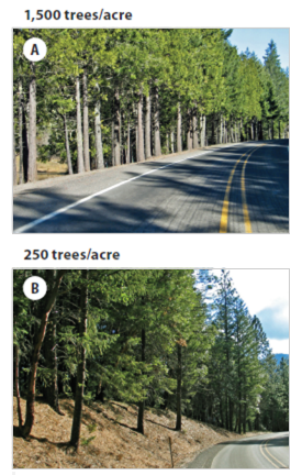 Figure 5-76 | Determining plant spacing
Determining plant spacing should be based on short- and long-term objectives. Where the short-term objective is quick visual screening and site stabilization, high-density plantings of 1,500 trees/ac (A) will produce the short-term desired outcome. These trees may need to be thinned to reduce competition to avoid creating an unhealthy stand of trees with a high fire risk. Reducing tree densities to 250 trees per acre will produce a mature stand of trees (B). Planting at these lower densities will reduce the need for thinning, but tree cover will take longer to dominate the site.
Photo credits: David Steinfeld
Select Stocktypes
Plants are grown, or cultured, in a variety of ways—indoors or outdoors, in native soil or artificial media, and for several months or up to several years. The nursery industry categorizes plants into “stocktype” groups based on plant age, size, and morphology. The “American Standard for Nursery Stock” provides a good summary of stock types and is considered the definitive reference for ensuring that plant size and container type conforms to the accepted industry standard. The American Standard for Nursery Stock deals primarily with commercial nursery stock and less with native forbs or shrubs. Individual stocktypes can be defined by the following:
- Plant type (bareroot or container)
- Years in the nursery
- Size or shape of the container for container stock
Plant Type—Nursery plants are grown in containers or bareroot in open fields. Bareroot seedlings are lifted from the nursery with their roots freed from the soil in which they were grown, while container stock is outplanted with its original nursery soil medium. Understanding the benefits and limitations of each system relative to the planting site can help designers choose the best plant types for success.
Root depth and configuration are important factors in successful seedling survival and site colonization. Bareroot seedlings often have a large, hardy shoot and root mass. This typically larger stem caliper and seedling hardiness may better withstand damage from animal browse than container stock. Root systems of bareroot stock are often limited to 12 inches or less due to culturing practices. In contrast, the wide variety of available container shapes and sizes provide the ability to develop target container seedlings with the optimal root mass based on the species and planting site conditions. The large root mass of bareroot seedlings can more readily colonize in native soils, but can be more difficult than container stock to plant in rocky, shallow soils. The fine roots more typical of container stock allow improved water and nutrient uptake, which is particularly important on drier soils.
Bareroot seedlings require more specialized handling and storage procedures than container stock. This can present challenges where timing of outplanting is variable or proper equipment is limited. Typical operations for bareroot seedlings include lifting in the winter (or before the ground freezes) and subsequent storage for several months. This may limit the planting window from early winter through late spring. Once they are lifted, bareroot seedlings are to be kept in coolers at the proper temperature and humidity to prevent respiration and mold development prior to planting. Operationally, container seedlings can be extracted, packed, and stored in a similar manner to bareroot. However, they may also be left in containers until planting is imminent allowing more flexibility in meeting operational timelines for planting. This allows for extending the planting season, or postponing until the following season if necessary. This method needs additional space for transport and storage, but eliminates the need for coolers and specialized handling.
Although bareroot seedlings are usually less expensive than container stock, for most roadside revegetation sites, container stock is recommended. Container stock is usually more appropriate for highly disturbed project sites. They are better suited to take advantage of limited soil moisture, which is a common limiting factor on these sites. The size and scale of these projects often require small numbers of multiple species which are more appropriate container seedling production. The extended planting window, often necessary to meet dynamic project timelines is more easily met using container stock.
Container Size—The size and age of a nursery-grown plant are controlled by the size of the container. Typically, the larger the container, the larger the plant and the longer it takes for roots to fill the container. In Figure 5-77, plants are grouped into broad categories based on how fast they typically fill out various container sizes. Many deciduous tree species, which include willows, cottonwoods, maples, alders, and ash, tend to be very fast growing species and can fill out a range of container sizes in just one growing season. Conifer species (firs, pines, cedars, and hemlocks) will fill smaller containers the first year and can be transplanted into larger containers for another one or two growing seasons. Faster-growing shrub species (ceanothus and bitterbrush,) are often grown in small containers in the spring and transplanted into larger containers several months later. They will fill a 1⁄8 to ½ gallon container in one growing season. It is good practice to keep slower growing shrub species in the smaller cells for a full growing season before transplanting.
Container Design—Container shape is also an important consideration in stocktype selection because it determines how easily the root plug is extracted from a container, the degree of root spiraling, what planting methods will be used during installation, and ease of handling (i.e., form factor). The depth and taper of the container walls govern how easily a root plug can be extracted from its container. Generally, the greater the taper, the easier a root plug can be extracted. Taper becomes more critical as container walls become longer with respect to the diameter of the opening. Straight-walled “tall pots,” made from PVC pipe, are very long in comparison to the diameter of the opening. Root plugs from this container are difficult to extract without the placement of seedling protector tubing inside the container. Pulling the seedling protector tubing during extraction brings out the entire root plug without undue stress to the stem or root system. Other nurseries offer tall pots with the PVC pipe cut in half lengthwise and held together with electrical ties. Before planting, the ties are cut, which allows easy access to the root system.
Several container design features affect root development and plant quality. When plant roots grow out and hit the sides of the container, they often grow downward in a spiral pattern. When roots reach the bottom holes, they can “air prune.” If kept too long in the container, the circling roots will eventually form a tight mesh which, after outplanting, can continue to circle and “strangle” the plant. Most containers have vertical ribs that guide roots down the sides of the container walls to prevent root spiraling. Some smaller containers feature copper coating on their walls to chemically prune the roots as they grow. Other container walls have vertical air slits that air prune the roots. When container roots are so cultured, the root system is more fibrous with more root tips which allows for vigorous growth when planted.
Root condition is a critical factor to discuss at the time that growing contracts are being developed. Roots that have excessive spiral growth can be pruned before they are planted, an activity most easily done at the nursery during harvesting. This extra processing step can be stipulated in the growing contract.
Matching Nursery Plants to Outplanting Site—A wide variety of nursery stocktypes are available (Figure 5-78). Site factors can be considered before placing an order. The depth and width of containers are very important for seedling survival and growth. Sites with low precipitation during spring, summer, and fall are often planted with larger container sizes. Where soil moisture-holding capacities are low or vegetative competition for soil moisture is high, long containers should be considered. Where rock content is high and it is hard to excavate a planting hole, shorter container stocktypes can be used. Additional post-planting care can compensate for shorter roots (Section 5.4.4). The planting method dictates the size of the root plug. For example, the expandable stinger and power augers require plug diameters no greater than 4 inches. Large seedling stems and tops are necessary where animal damage is expected.
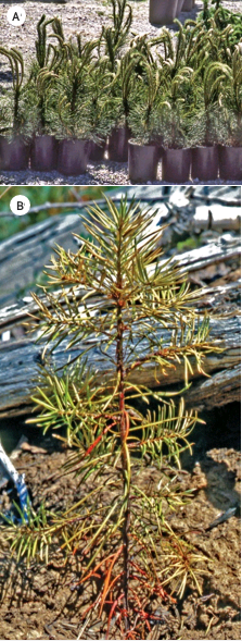 Figure 5-79 | Well-balanced nursery stock
The shoots of these pine seedlings have grown too large for the size of the root system, which increases moisture stress after planting. In addition, the buds have broken dormancy, which means the plants will not tolerate rough handling (A). Poorly balanced or conditioned nursery stock will struggle to survive and grow after planting and exhibit signs of "transplant shock" (B). Photo credits: Thomas D. Landis
Figure 5-79 | Well-balanced nursery stock
The shoots of these pine seedlings have grown too large for the size of the root system, which increases moisture stress after planting. In addition, the buds have broken dormancy, which means the plants will not tolerate rough handling (A). Poorly balanced or conditioned nursery stock will struggle to survive and grow after planting and exhibit signs of "transplant shock" (B). Photo credits: Thomas D. Landis
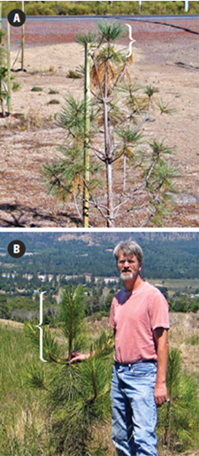 Figure 5-80 | Effects of transplant shock can last years
The ponderosa pine seedling (A) was grown for four or five years at a nursery and outplanted on a semi-arid site. The photograph was taken one year after outplanting and shows the seedling has undergone transplant shock due to the imbalance, or high shoot to root ratio, of the seedling when it was planted. The seedling was root-bound when it was planted. The tree responded by dropping most of its nursery needles and grew very little in height in the first year. A different ponderosa pine seedling (B) was grown in a one-gallon container for one year, then outplanted. Because this seedling had good balance and was not root-bound, it did not undergo transplant shock after it was outplanted. After two years, this seedling is well established. The brackets in both photos show the current year leader growth. Photo credits: David Steinfeld (A) and Greg Carey (B)
Figure 5-80 | Effects of transplant shock can last years
The ponderosa pine seedling (A) was grown for four or five years at a nursery and outplanted on a semi-arid site. The photograph was taken one year after outplanting and shows the seedling has undergone transplant shock due to the imbalance, or high shoot to root ratio, of the seedling when it was planted. The seedling was root-bound when it was planted. The tree responded by dropping most of its nursery needles and grew very little in height in the first year. A different ponderosa pine seedling (B) was grown in a one-gallon container for one year, then outplanted. Because this seedling had good balance and was not root-bound, it did not undergo transplant shock after it was outplanted. After two years, this seedling is well established. The brackets in both photos show the current year leader growth. Photo credits: David Steinfeld (A) and Greg Carey (B)
Stocktype selection often determines seedling survival rates and how fast they grow in the first years after planting. Typically the larger the root system, the better the survival and growth. Larger stocktypes cost more, so it is important to target the stocktype to the needs of the site and the revegetation objectives. For example, if quick establishment of vegetation for visual screening is an important objective, then a large stocktype would be ordered. Alternatively, if a revegetation unit is relatively unseen and the site has few limitations to plant survival, a small, less expensive stocktype would be ordered. While larger stocktypes are generally more expensive than smaller stocktypes, the total costs of establishing seedlings is an important consideration to make before settling on a smaller plant. Costs for replanting a site where smaller seedlings died in the first year can be far more expensive than planting larger plants in the first place.
Years in the Nursery—Bareroot stocktypes are often defined by the years they are grown at the nursery, whereas container plants are typically described by the size of the container. This is important when ordering plants because many species take longer than one year to grow to the desired plant size. If plants are needed for a project within one year, the designer will need to order smaller size containers to ensure that the roots can fill the plug.
Unbalanced or Holdover Stock—A common mistake is growing container plants with tops larger than the root system can support. This is often the result of poor planning, delay of projects, or poor selection of stocktype. For example, road projects are frequently delayed for a year, leaving the designer with the problem of what to do about the seedlings that are being grown. Typically under these circumstances the nursery manager is asked to hold the seedlings in the same containers an extra year. While most will comply, they will do it reluctantly. The result is plants that are top heavy—the shoots are too large for the root system to support (Figure 5-79A). The results are often deceiving. The plants have not shown stress because they have been pampered under greenhouse conditions and care. Yet, once seedlings are outplanted on a typical harsh site, the plants will struggle to grow enough roots to keep the tops healthy and alive. Plants respond to the lack of moisture in what is referred to as “transplant shock (Figure 5-79B) by shutting down growth and often turning yellow or “chlorotic.” Roadsides are stressful sites that typically require the very best quality plant material. A good example of the difference between well balanced and poorly balanced nursery stock is shown in Figure 5-80.
Delays are common in roadside projects, so two viable options can be considered: transplant the stock into larger containers or reject the plants and place a new order. Option one is appropriate if the plants are being grown in small containers and a larger container is available for transplanting. If growing plants in a large container, it makes little sense to transplant into a still larger one. This option is often more costly than option two, which is to start over with the order, but starting over assumes available seeds and other starter plant materials are available and there is enough time to reorder. For plants that are not used, the designer or nursery manager can contact land managing agencies and landowners in the general geographic area to determine if they are interested in these plants. If not, watershed councils or environmental groups often appreciate the donation of such plants for their projects.
Develop Growing Contract
All nurseries experience weather extremes, insect or disease losses, equipment failures, and other production problems that can severely decrease the quantity and quality of the stock. Therefore, it is a good strategy to reduce these inherent risks by growing plants at more than one nursery. In doing so, the strengths and weaknesses of each nursery can be determined, which is helpful for future orders.
Nursery Selection—Very few nurseries will offer plants from source-identified plant materials specific to a project, even in geographic areas of the country with an abundance of nurseries that grow native plants. Obtaining genetically appropriate plants means finding nurseries willing to grow seedlings from specified genetic material. A current national list of native plant nurseries can be found online in the National Nursery and Seed Directory (Inset 5-17).
When considering a nursery for plant production, consider the following factors:
- Proximity—Is the nursery close enough to visit occasionally?
- Service—Is the staff easy to contact? Do they promptly return phone calls or e-mails? Are they friendly and helpful?
- Expertise—Are they knowledgeable in restoration and revegetation?
- Years in business—Has the nursery been in business for at least three years?
- Seedling quality—Is the overall seedling quality high?
- Seedling quantities—Are the orders regularly met or do they consistently run short?
- Price—Are prices competitive?
- Willingness—Will the nursery try new things?
If there are doubts about one or more of these factors, consider using another nursery. Ultimately, the selection comes down to personal experience with nurseries and word-of-mouth from other designers.
Seedling Orders—A plant production contract can detail the information developed in previous sections of this chapter:
- Species
- Genetic source
- Starter plant material
- Stocktype
- Net amount of plants
- Month and year for plant delivery
- Minimum seedling specifications
- How they will be processed and stored
A few phone calls to nurseries will provide an idea of which nurseries will grow the species, stocktype, and quantities necessary for the project. Nurseries can still be used if they can only meet a portion of the order. Other nurseries can produce the remainder because there is less risk by sending plant orders to several nurseries. Contracts can be developed once it is known what portions of an order a nursery can produce.
Plant Processing and Storage—Once seedlings have reached the target size and age at the nursery, they are harvested, stored, and processed for shipping. If the plants are bareroot seedlings, they are lifted from the soil, graded, and packaged. Container seedlings can be extracted from the containers, graded, and packaged, or sent to the planting site in containers and extracted immediately before planting. Either way, most stocktypes will be held at the nursery for one to six months, depending on when they are needed for planting. “Planting windows” are described in more detail in Section 5.4.4.
Storage times are longest for seedlings planted in the late winter and spring. For these orders, plants are extracted from their containers or lifted from the soil in the winter when they are least susceptible to the stress or damage associated with extraction, handling, and packaging. Plants in this condition are dormant. The onset of plant dormancy for deciduous plants is often around the time when plants have lost their leaves in late fall; the end of dormancy begins just before the buds begin to swell in late winter to spring. The dormancy period for conifer species is not visibly discernible, but typically follows a similar time frame as deciduous species. Seedling dormancy in the western United States typically extends from December through February, but the dates will vary by nursery. If plants are to be extracted and held in cold storage for long periods, it is important to know when the nursery is extracting and handling the seedlings to be sure these operations are done when seedlings are dormant. Seedlings that are extracted or lifted outside the seedling dormancy period and stored for any length of time will survive and perform poorly.
When plants are lifted from bareroot beds or extracted from containers, they are also being graded for size and appearance. Unless otherwise agreed, the size specifications stated in the contract will be the grading criteria (Figure 5-81). It is helpful to be at the nursery during lifting/ extraction and grading to see which seedlings are being thrown away and which seedlings are considered shippable. Bareroot and smaller container plants are graded and boxed for refrigerated or freezer storage. Storage containers will have important information about the plants, such as seedlot, date packed, client name, and the number of seedlings in the container. Plants are typically held in cooler storage (32 to 35 degrees F) from a few weeks to two months. If longer storage is required, freezer storage (28 to 31 degrees F) is recommended to maintain seedling quality and reduce the chance for storage molds.
Inset 5-17 | Forest Service Nurseries—Dorena Genetic Resources Center
US Forest Service Nurseries have a long history of growing plants that are genetically appropriate and locally adapted for use in reforestation and restoration of public lands (Dumroese and others, 2005). These nurseries also establish new growing protocols, continue to improve cultural practices, and provide technology transfer in seedling production and quality. While the focus of most nurseries is on plant production, the USFS Dorena Genetic Resource Center (Cottage Grove, OR) nursery has expanded its services to more effectively accomplish restoration to meet the needs of its diverse clientele. Dorena has become the primary plant development center for the USFS Restoration Services Team (RST), created in partnerships with Western Federal Lands and OR and WA State Departments of Transportation. This membership in the RST is the driving force for expanding the nursery capabilities to a full service restoration center.
The restoration species at right are grown at the USFS Dorena Genetic Resource Center nursery and used on RST restoration projects.
Dorena offers complete services beginning with project initiation through successful site restoration. Beginning with project consultation, including recommendations on stocktypes, species mix, plant quantities, and timing, their staff provide knowledgeable input matching plant materials to the client’s specific project needs. Following this initial consultation, a range of other services are available to help clients fulfill their project objectives. These include the following:
- Assistance in on-site seed and vegetation collection;
- Container plant production of native conifers, hardwoods, shrubs, forbs, and grasses;
- Development and technology transfer of propagation protocols for species without established growing regimes;
- Specialize in small quantity, multiple species orders, and difficult to grow species;
- Consultation and assistance in outplanting including development of innovative tools and techniques;
- Full range of project monitoring design and implementation;
Assistance with restoration project management through the RST.
Dorena continues to strengthen and expand its partnership base and its role in providing innovative solutions to current biological challenges. For example, current emphasis on pollinators has resulted in Dorena growing a variety of plant species specific to enhancing pollinator habitat. The nursery continues to adapt to new challenges in meeting the changing needs of restoration.
Large container stocktypes (typically those equivalent to a half gallon or larger) are stored and transported in the containers in which they are grown. They are typically stored in shadehouses or other sheltered storage. In cold climates, the roots can be insulated to protect against cold injury. During unseasonably warm periods in late winter or early spring, large container stock can be monitored for drying and irrigated if necessary.
Grading Specifications—Although it is an excellent resource, the American Standards of Nursery Stock deals primarily with plants of horticultural origins it does not adequately provide standards for the growth patterns of native species. Therefore, a good practice is to establish criteria for accepting or rejecting plants. Being present at the time of packing is the most effective way to negotiate grading standards with the nursery and ensure that quality plants are received.
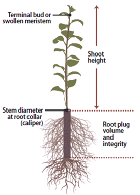 Figure 5-81 | Seedling grading criteria
Grading criteria for seedlings are based primarily on stem diameter, height, terminal bud, root volume, and integrity.
Typical grading standards can be divided into the following categories (Figure 5-81):
- Root system—It is good practice to examine the root system of the plant carefully. A healthy, vigorous root system is one of the most important determinants of plant survival and growth, especially in low rainfall areas and challenging revegetation sites. For bareroot stock, healthy roots are characterized by being well developed and fibrous and having approximately the same area as the crown. For container stock, healthy root “plugs” should be firm but not root-bound. Healthy roots typically are not spiraled or in a tight mass at the bottom of the seedling container.
- Stem diameter at root collar (caliper)—Stem caliper is another important morphological measure of nursery plant quality and has been consistently correlated with outplanting survival and growth. Diameter is not necessarily a good measurement for rooted cuttings because the size of the stem is dependent on the original diameter of the cutting. A typical grading specification for many bareroot and container stocktypes is a minimum diameter of 3.5 to 4.0 mm for one-year-old seedlings, and greater than 4.0 mm for plants grown for two years. Discuss these specifications with the nursery because not all species will grow to these sizes in this time frame.
- Shoot height—The height of the plant is measured from the root collar, or original ground line, to the top of the terminal bud. Some species do not form a terminal bud, so the swollen meristem tip or even the average top of the crown is used.
- Seedling balance—Quality nursery stock typically has a good ratio between the amount of foliage and the root system. This is traditionally expressed as a shoot-to-root ratio (S:R) and typically ranges from one or two part shoots to one part roots (an S:R from 1:1 to 2:1). This grading standard is a qualitative determination as to whether the root system is large enough to support the above- ground portion of the plant.
- General plant health—During grading, nursery stock can be inspected for physical injury or disease. Root disease is a particular hazard of container stock, and soft or moldy roots are suspect (Inset 5-18). Scraping the roots with the blade of a knife is a way to reveal whether white healthy tissue is present.
Administer Contract
The nursery manager can be required to maintain records on how the plants were cultured. Basic information includes date plants were started; the type, rates, and timing of fertilizer applications; irrigation schedules; greenhouse settings (temperature, lighting, humidity); pesticide applications; and any significant problems that might have occurred with the seedlot. The nursery can also be required to provide an accounting, or inventory, of the plant orders by late summer.
It is important to visit nurseries at least yearly, but more often is better. These visits will provide an indication of the quality of the stock that will be received and whether the number of seedlings ordered is being met. It also helps strengthen the relationship between the designer and the nursery manager, which often leads to more attention being given to the orders. One of the best times to visit is during the initial plant establishment phase in late spring or early summer after seeds have germinated or seedlings and cuttings have been planted. Stock problems are most likely to be observed at this time. If there is a fall-down in the inventory or the seedlings look unhealthy, this can be discussed with the nursery manager. If caught early enough, there can be time to start more plants. At a minimum, the early identification of problems will provide time to adjust the planting plans and other contracts that depend on the plant inventory.
Another important time to visit the nursery is during the processing of plants for storage or shipment to answer questions that might arise about grading specifications, packaging materials, pruning, and other operations. It also provides a good idea of what type of stock will be received when it is shipped to the planting areas to avoid any unwelcome surprises.
Inset 5-18 | Assessing poor quality nursery stock
Poor quality planting stock can be caused by biotic (e.g., diseases, insects) or abiotic factors (e.g., imbalance of soil moisture, temperature, nutrients, and pesticides) in the nursery resulting in detrimental, and sometimes devastating, effects on seedling survival and growth when outplanted. Infection with various pathogens, or biotic causes, may not necessarily be manifested in a nursery but may cause stunting or mortality once seedlings are under stress following outplanting. It is helpful for designers to be aware of the possible nursery diseases in order to either recognize or discuss with nursery personnel during visits to inspect their seedlings.
Diseases caused by fungi, water molds, bacteria, and viruses can often be difficult to distinguish from damage caused by abiotic events or factors. If damage or chlorosis of seedlings is noted, it is recommended to check with the nursery manager to determine the history of the seedlings, what pathogens are traditionally a problem at the nursery, and what, if any, have occurred during the current growing season. Hamm et al (1990) and Landis et al (1990) provide more detailed information on nursery pests.
Shoot and foliage diseases can be caused by a variety of organisms, with various levels of impact on seedlings. Fusarium hypocotyl rot (caused by Fusarium oxysporum) can cause large losses in the nursery from July through October. Gray mold (caused by Botrytis cinerea) can cause significant damage to densely grown bareroot and container seedlings, as well as nursery stock stored in less than optimal conditions (Hamm et al 1990). The mycelium and gray spore clusters are often easily visible to the naked eye. Botrytis can girdle infected seedlings, increasing mortality rates following outplanting. Minor shoot and foliage diseases, such as shoot blight (caused a number of organisms, including Sirococcus spp., Phomopsis spp., and Phoma spp.) and needle-casts and other foliage diseases tend to deform or stunt seedlings but do not result in significant mortality in the nursery or in an outplanting situation.
Root diseases may be the most insidious of nursery seedling diseases. Because seedlings are cultured under optimum conditions for growth, symptoms are often masked throughout the growing season, manifested only during outplanting stress or drought stress in succeeding years. Most conifers, and many native species, are susceptible to root diseases and root rots caused by Phytophthora spp., Fusarium spp., and Cylindrocarpon spp. These diseases are manifested in the nursery in pockets of symptomatic seedlings or mortality, particularly in areas of poor drainage or previous infestation. Outplanting seedlings infected with these pathogens will result in reduced survival. In addition, transfer of these organisms to outplanting sites may result in infection of the planting area. This specifically is a problem with the root disease Phytophthora lateralis. The spread of this disease from infected seedlings can devastate populations of established Port Orford cedar.
Not all seedling quality problems are caused by biotic factors—many are one-time damaging events that occur during a short span with a regular distribution throughout the field or greenhouse (Mallams 2006). If foliage discoloration, foliage or stem wilting or die-back, seedling stunting, or mortality occur in large patches or over large areas in the nursery, the causes are often abiotic. Outplanting seed- lings that have been stunted or damaged in the nursery can reduce seedling growth and survival, as well as increase the time required for site recovery. However, the symptoms of abiotic damage are often more apparent, and the consequences more easily predictable, than damage caused by pathogens.
Although designers have little to do with nursery cultural practices and disease mitigation in the nursery, several options exist to prevent or control disease problems on restoration sites. Disease mitigating measures are similar to insect mitigating measures: (1) only plant healthy stock because weakened or stressed seedlings are more susceptible to diseases both in the nursery and on the outplanting site, (2) plant a variety of species to avoid outplanting failure due to infestation of any single disease, and (3) create a healthy soil environment—seedlings grown on poor sites or on sites outside of the species environmental ranges will be stressed and more susceptible to disease infection.
Back to top
5.4 INSTALLING PLANT MATERIALS
Once the project site has been prepared (Section 5.2) and the plant materials have been obtained (Section 5.3) the vegetation can be installed on the project site. The following implementation guides cover the methods for installing seeds, cuttings, and plants. Section 5.4.1 discusses the different methods of seeding, how to formulate seed mixes, determining seeding rates, and ensuring quality. A specialized form of seeding, hydroseeding, is discussed in Section 5.4.2. Section 5.4.3 outlines cutting installation techniques most commonly used in biotechnical engineering designs. Section 5.4.4 discusses techniques for planting bareroot and container plants. It also discusses seedlings, plant handling, storage, and quality control measures.
5.4.1 SEEDING
Introduction
Seeding is the distribution of seeds for the purpose of establishing seedlings at a desired density and species composition. In addition to careful site preparations and seed treatment, optimal seeding operations incorporate how seeds are uniformly distributed over an area; where seeds are placed vertically (that is, in, on, or under the soil surface); species composition in the seed mix; and when seeding takes place. These factors can be adapted to each revegetation unit to account for the unique climate, soils, and species requirements.
Seeding is often coupled with other operations, such as fertilization, soil amendment applications, and soil stabilization treatments. While accomplishing these objectives at the same time as seeding often makes practical sense from an economic and scheduling standpoint, it might not always be best for the short-term establishment of native vegetation. It is important to consider the effects of combining too many operations into the sowing operation. It may be necessary to plan some of these operations at different times. For example, fertilizing, which is often done during the seeding operation, might best meet objectives if applied separately from seeding (Section 5.2.1).This section describes the seven steps in developing a seeding plan: (1) identifying seeding areas, (2) determining seed application methods, (3) developing seed mixes, (4) determining sowing rates, (5) preparing seed mixes, (6) selecting sowing dates, and (7) applying seed and ensuring quality.
Identify Seeding Areas
It is important to visit the project site as soon as possible and specifically identify seeding areas on the ground. If road construction is a multi-year project, finished slopes can be assessed for seeding while the remaining construction continues. This may be the case if water quality permits are required given that they have specific timeframe requirements for slope stabilization (i.e., earthwork must be permanently stabilized with 14 days of completion). While most seeding areas will conform to the revegetation units developed during planning, sites often look different after construction. A field review notes where topsoil has been placed, the presence of surface rock, surface roughness, accessibility by equipment, microclimate, soil compaction, and other site factors. These factors will be used to develop seeding methods, sowing dates, seed mixes, and seeding rates for each of the seeding areas.
Seeding areas are located on a map and by road station. For each seeding area, acreage can be calculated using the methods described in Table 5-1. These calculations consider the areas where seeding will actually occur. For example, seeds typically are not applied in areas where herbicides will be used for maintenance. At the end of the field survey, the total acreage for each seeding area can be summarized and used to develop seed mixes for each seeding area (Section 5.4.1, see Prepare Seed Mixes).
Determine Seeding Methods
A variety of methods for applying seeds are available to the designer. A challenge lies in matching these methods to the sites encountered in mountainous terrain. Typically, the site characteristics of each seeding area will dictate the type of seeding method used. For example, a road project might have three revegetation units: a steep, north-facing slope; an obliterated road; and a rocky south slope. Hydroseeding could be planned for the steep, north-facing slope where other equipment cannot reach. On the obliterated road, several ground-based seeding methods could be used, including mixing seeds into the soil or broadcasting on the surface and covering with a mulch. The south-facing slopes could be hand-seeded, then covered by a mulch to keep the seeds from drying out during germination or hydroseededing a bonded fiber matrix mulch. Each project will most likely have site-specific seeding strategies to provide optimal conditions for seed germination.
Moreover, each plant species have unique seed covering requirements. While seeds of most species are best buried in the soil or covered by mulch to germinate, some species require partial exposure to light to germinate and are not to be covered very deeply. A general rule for seed covering is to bury seeds at depths from twice (Munshower 1994) to three times (Monsen and Stevens 2004) the seed diameter. The deeper the seeds are covered, the less likely they will dry out during germination. The tradeoff, however, is that seedlings will have to expend more energy to emerge from deeply buried seeds. This can ultimately affect early seedling establishment.
For the Designer Because broadcast seeding often results in poor seedling establishment, 50 to 75 percent more seeds should be used in broadcast applications.
The ideal seedbed, as defined in Monsen and Stevens (2004), is “one in which the seed is firmly enclosed within soil particles to provide hydraulic conductivity of moisture to the seed. Seeds should be placed deep enough to prevent rapid drying but shallow enough to allow natural emergence.” Creating an ideal seed environment is an important practice, especially in nurseries, farms, or gardens where the objective is to create a uniform plant crop. It is good practice for all operations in these settings to be standardized and uniform (e.g., correct seed depth, optimum lighting, uniform irrigation, and uniform seed densities). While uniformity and standardization can be applied to wildland revegetation, an alternative strategy could be considered. This strategy starts from the premise that information about the specific germination and early seedling growth requirements of different native species at each seeding site is difficult to obtain. For this reason, a variety of environments, or “regeneration niches” (Grubb 1977), can be created where seeds might find the right conditions for germination (Figure 5-82). Further, a range of native species can be applied to fill these environments. With roadside revegetation, uniformity is not the objective. In fact, some randomness will most likely fit with the surrounding plant communities.
Vertical seed placement, where seeds are vertically distributed in soil or mulch layers, can be grouped into the following categories:
- Broadcast onto the surface
- Pressed into the soil surface
- Mixed under the soil surface
- Drilled under the soil surface
- Covered with long-fiber mulch
- Mixed into long-fiber mulch
- Covered with hydromulch
- Mixed into hydromulch
Vertical seed placement methods are discussed in the following sections in the context of how they affect germination and seedling establishment.
Seeds Sown on the Soil Surface—One of the most common forms of seeding is broadcast seeding, which is casting seeds on the surface of the soil with a rotary spreader or by hand. Broadcast seeding is almost always the least expensive form of seeding. Rotary spreaders can be attached to most types of vehicles, including all-terrain vehicles and pickups, and used where vehicle accessibility is adequate. Where slope gradient or accessibility limits mechanical seeding, the use of a hand-held broadcast seeder is a viable option. Because of this, although manual broadcast seeding might be considered a low-tech method, it still has an important place in revegetation.
Figure 5-83 | Seed mix on variable substrate
Broadcast seeding leaves seeds exposed on the soil surface where they have reduced contact with the soil.
Figure 5-84 | Seeds pressed into soil surface
Pressing seeds into the soil surface improves germination by increasing seed-soil contact.
Figure 5-85 | Seeds mixed under soil surface
Seeds mixed under the soil surface puts them in direct contact with the soil, greatly improving germination.
Manual broadcast seeding offers the opportunity to spot-seed microsites at different seed rates and seed mixes. For example, two people could hand seed a steep cut slope requiring two different seed mixes—the lower portion of the slope sown with a grass and forb seed mix and the upper portion with a shrub and seed mix. In another instance, a fill slope composed of rocky outcrops interspersed among deep soils is composed of two distinct microsites that could be seeded separately with different seed mixes. With knowledge of the road objectives, several hand seeders can apply seeds across a project area that mimics the vegetative patterns of the landscape. Spot-seeding can also be a method of applying valuable seeds or “unique” species to strategic locations. For example, showy forbs that may have benefits to pollinators might be expensive to obtain or require a specific habitat can be spot-seeded in those locations.
The disadvantage of broadcast seeding is that seeds are not covered by soil or mulch (Figure 5-83). Because seeds need intimate contact with soil to germinate, broadcast seeding typically results in low establishment of seedlings. If greater quantities of seeds are sown; however, some seeds will find microsites with high humidity (between surface gravels or rock) or will be covered by soil particles that have been moved through erosion processes. Sowing an estimated 50 to 75 percent more seeds can compensate for the inability of seeds to germinate or the loss of seeds to rodents (Monsen and Stevens 2004). It is important to adjust survival factors downward when calculating sowing rates for seed mixes (Section 5.4.1, see Prepare Seed Mixes). Broadcast seeding on roughened surfaces can potentially increase germination rates, especially if seeds are sown in the fall. The probability that seeds will be covered by sloughing soil over time is increased (Stevens and Monsen 2004), so it is important that the soil surface be left as rough as possible where broadcast seeding will be used.
Seeds Pressed into the Soil Surface—Seed that is sown on the surface and pressed into the soil increases germination rates over broadcast sowing. Seeds are in firm, intimate contact with the soil that increases available water to the seeds (Stevens and Van Epps 1984, Figure 5-84). Imprinting produces a variety of microsites that may benefit the germination of multiple species (Stevens and Monsen 2004). This type of seeding is accomplished with imprinting equipment (Section 5.2.2, see Roughen Soil Surfaces). In this operation, seeds are dropped from a seeder mounted in front of the imprinter and then pressed into the soil. Imprinting works well for small- to medium-sized seeds; seeds are in firm contact with the soil but not buried too deeply to affect seedling emergence. In some cases, imprinting small- and medium-sized seeds can result in germination as good as, or better than, drilling seed (Haferkamp et al 1985). Covering larger seeds by soil or mulch can help ensure adequate germination. Imprinting seeds cannot occur on steep slope gradients or slopes with high rock content. Sites that are too steep for tractor access are too steep for current imprinting equipment.
Seeds Mixed under the Soil Surface—Mixing seeds into the surface of the soil is one of the best ways to achieve optimum germination (Figure 5-85). Mixing is done in two stages: seeds are applied on the soil surface by either broadcast seeders or by using a seedbox and drop tubes, and then seeds are incorporated into the soil by dragging anchor chains, disk chains, cables, pipe harrows, or other implements behind a tractor or other all-terrain vehicles. Specialized, equipment has been developed for wildland conditions that will apply and incorporate seed in one operation. The “ripper-seeder-harrow” (Figure 5-86) is a specialized seeder that simultaneously subsoils, broadcasts seeds, and mixes in one operation. Use of this equipment is limited to slope gradients of 1V:3H or less and non-rocky soil surfaces.
On steeper slopes, any method that scarifies the soil surface after seeds have been broadcast will mix the seeds into the surface (Figure 5-87). Using a hand rake to incorporate broadcast seeds into the surface works well and can be used in areas where expensive or valuable seeds have been applied. This type of seed placement usually requires that the seed depth be monitored to ensure that it is not buried too deeply. It is good practice to mix seeds no deeper than one inch.
These application methods allow seeds to be mixed evenly through the soil and not be concentrated in rows, as they are with drilling (see below). However, soil is left loose around the seeds, which decreases water-holding capacity and seed-soil contact. If seeds are sown in the fall and do not germinate until the following spring, natural packing of soil around the seeds will occur.
Seeds Drilled under the Soil Surface—Using a seed drill is another method for covering seeds with soil. Seeds are not actually drilled into the soil, as the name implies, but sown just under the surface in rows. Seed drills first open the surface of the soil with a disk or tine; drop seeds from a seedbox through tubes into open furrows; close the furrows with a disk; and finally pack the soil firmly around seeds with a press wheel. Cropland drills have been developed for the agricultural industry. However, this equipment has limited applicability on highly disturbed sites because rocky soils and uneven soil surfaces create difficulties in placing seeds at proper soil depths. Several drills have been developed for rangeland restoration that compensate for these limitations. The Rangeland and Truax® drills were specifically developed for seeding rocky, uneven surfaces and would work well on roadsides with shallow cross slopes. The Truax® drill was an improvement on the Rangeland drill and includes three seed boxes that can independently distribute seeds at different depths corresponding to the size and shape of the seeds (Stevens and Monsen 2004).
Figure 5-88 | Seeds drilled under soil surface
Seed drills place seeds in rows under the surface where they are in direct contact with the soil.
Figure 5-89 | Seeds covered with long-fibered mulch
Covering broadcast seeds with long-fibered mulch is effective in conserving moisture around the seeds.
Figure 5-90 | Seeds mixed into long-fibered mulch
Seeds mixed into long-fibered mulch have less contact with soil, which can reduce germination.
Seed drills concentrate seed into rows (Figure 5-88), creating a greater potential for competition between emerging seeds within rows than if seeds were broadcast. For example, a seed mix with an aggressive species will emerge and dominate the row of seeds at the expensive of less aggressive species. The three seedboxes on the Truax® seed drill can be used to compensate for this potential problem. The less aggressive species are placed in separate seedboxes and sown in separate rows. If more than one seedbox is used, separate sowing rates can be calculated for each box. Moreover, the three seed boxes can each accommodate a different type of seed such as very small or large seeds or fluffy seeds. The various seedboxes allow for these seeds to be sown separately into different rows to account for sowing rates. Typically, lower seed rates are used in drilling operations because the seeds are concentrated in rows and closer together. Fewer seeds are also used because of increased seedling establishment due to the improved seed-soil contact that results from using this equipment and technique. Where rodents are present, drilled seeds are more prone to being excavated by rodents that simply follow a row of seeds (Stevens and Monsen 2004).
Seeds Covered with Long-Fibered Mulch—Optimum seed germination is obtained under long-fibered mulch. The mulch provides a moisture barrier that protects seeds and keeps soil from drying (Figure 5-89). Soil moisture is maintained longer around seeds than if they were only covered by soil. This is a two-stage operation in which seeds are broadcast on the soil surface and then covered by mulch. The thickness at which the mulch is applied depends on the seed size and the type of mulch. Small seeds likely require less cover than large seeds. The rate at which mulch can be applied varies by the characteristics of each type of mulch. Wood strands and straw, for example, can be applied at higher rates (thicker layers) than composts or chips because more light is able to penetrate these mulches, allowing seed germination and seedling establishment. Refer to Section 5.2.3 for further discussion of mulches.
Sowing seed mixes that contain a variety of seed sizes requires that the mulch not be uniformly applied. One strategy is to begin with a roughened seedbed, as shown in Figure 5-86. Because the surface is not even, mulch will settle in depressions and be thicker than on the ridges. Monitoring the application rates is important to ensure that seeds are covered with the proper mulch thickness. While covering seeds with long-fibered mulch is the most favorable method for optimum seed germination, it is also the most expensive. On slopes tackifier can be used to strengthen the cross linking of fibers and the mulch’s bond with the soil.
Seeds Mixed into Long-Fibered Mulch—Seeding and mulching are often combined into one operation (Figure 5-90). Most mulch blowers have seed metering systems that distribute seeds with the mulch as it is being applied to the soil surface. Seeds in this operation are distributed within the mulch, as opposed to being placed between the soil surface and mulch layer. Although combining these applications in one operation is more efficient, seed germination and seedling emergence rates are typically lower than when seeds are broadcast on the surface and covered with mulch. When seed is mixed with the mulch, much of the seed will end up on the surface of the mulch and not in contact with the soil. Unless the mulch has a high water-holding capacity, moisture around the seeds will be limiting during germination and seedling emergence. It is important to know how much moisture a mulch can hold when deciding whether seeds will be mixed with the mulch or broadcast applied first then covered with mulch (Section 3.8.1, see Rainfall Interception) for determining moisture-holding capacities of mulches). Composts, for example, have high water-holding capacities, and seeds will typically germinate well in this material; ground or shredded wood mulch and wood strands have very little water-holding capacity and seed germination will be lower. Seed rates will likely increase relative to how much moisture the mulch is expected to hold. For low water-holding capacity mulches, seeds in the upper portions of the mulch will not germinate or will germinate poorly. Seed rates in this type of mulch can be increased by 25 to 50 percent.
Figure 5-91 | Seeds applied in hydromulch
Because of numerous factors such as application rate and site topography, application of seeds in a hydromulch often results in a portion of seeds on the soil surface and some suspended in the hydroseeding matrix above the surface.
Seeds Applied in Hydromulch—When seeds are applied through a hydroseeder (Section 5.4.2), they will lay on the soil surface surrounded by a covering of fine-textured wood fibers (Figure 5-91). Contractors sometimes apply seeds in hydromulch at less than the manufacturer’s application rate and when this occurs seeds will be covered with less than 0.25 inch of mulch, with some seeds not covered. As rates approach 3,000 lb/ac, mulch thickness increases to over inch, with most seeds being covered. Some products have a recommended application rate of 4,500 lb/ac. Hydromulch has a high water-holding capacity, maintaining thousands of times its dry weight in water. This can be beneficial to seeds during germination. However, unless very high rates of hydromulch are applied, many seeds in the slurry are not covered by the hydromulch. Some hydroseeding operations try to apply a thin mulch slurry with tracer dye and tackifier and with all the seeds first and then covering the seeds with hydromulch in a second pass. Critically, the total mulch thickness will be determined by the second pass. Hydroseeding is a common method of seeding for roadsides because large areas can be covered in a short time and it holds seed in place with the soil to germinate. Some damage to the seeds can occur through the pumps and agitators or by hitting the ground at very high speeds during application.
Hydroseeding is one of the most common methods of applying seeds to road construction disturbances. It is often the only way to place seeds on steep, rough terrain encountered in mountainous regions. Hydroseeding strategies that maximize good germination include increasing the amount of seeds, applying seeds in the first pass then covering with hydromulch in the second pass, and applying rates of mulch not less than manufacturer’s recommendations. Fall hydroseeding also increases establishment rates.
For the Designer
Seed rates should be increased 20 to 50 percent for application with low water-holding capacity mulches.
Over-wintered seeds are ready to germinate on the first warm days of late winter or early spring when humidity levels are high. In addition, hydraulic mulches are more likely to stay moist for longer periods. Hydroseeding is simpler than dry seeding because there is no seed metering system; seed mixes are simply mixed into the hydroseeder tank and applied. However, even though there is no metering system, applications can be calibrated, therefore having well-trained applicators a key for successful hydroseeding. Refer to Section 5.4.2 for more discussion on hydroseeding.
Seeding with Compost Blanket—A recent addition to seeding methods is the use of the compost blanket. This can be seed, tackifier and medium (or coarse) compost applied in a 2 inch thick layer, but because many seeds are too deep in the compost matrix, a better method is to apply a 1 ½ inch thick layer of medium (or coarse) compost with tackifer to a prepared slope, then apply another ½ inch layer of compost with tackifer and seed. A third method is to install the 2 inch layer of compost, tackifers and hydroseed on top of that. The compost when tacked in place, provides erosion control, retains moisture (but not too much, that is the reason fine compost is the wrong material for compost blankets) and the dark color of the compost captures heat that helps germination. The compost material adds organic material to the site which provides the seeds with nutrients and it jump-starts the development of a soil biotic community. On steep slopes measures may need to be taken to key the compost blanket in place, like installing straw wattles, staked in place, prior to installing the compost.
Formulate Seed Mixes
The seed mix refers to the species composition being applied over a seeding area. It is important to avoid applying a single species to a site. Because highly disturbed sites typically are extremely variable in soil temperatures, fertility, soil moisture, solar radiation, and other site factors, it is important to apply a number of species in a seed mix to ensure that all possible microsites are populated (Monsen and Stevens 2004). Microsites that are unfavorable to one species might be favorable to others. Applying a mix of species also ensures that if there is a problem with the germination of one species, the other species will fill in. It is good practice to base the composition of seed mixes and sowing rates on the growth habits of each species and the soils and climate of the site.
It is preferable to avoid mixing slow-growing species with fast growers because the fast growers will out-compete the slow growers for space and resources (Monsen and Stevens 2004). Separating slow growers from fast growers is not always possible. Effective seed quantities therefore reflect higher ratios of slow growers to fast growers to achieve some degree of success. Shrubs and trees are typically less aggressive than grasses during the establishment phase and can be applied in a separate mix or planted as seedlings. Grasses tend to be more aggressive than forbs. However, if the Truax® seed drill is used, they could be applied in the same area but in different rows using the separate seed boxes. Although this does not guarantee that the grasses won’t out-compete the forbs therefore the preferable approach is to seed the forbs separately if possible (e.g. forb “islands” or patches). Some species take several years to develop. A mixture of fast-growing annuals and slow-growing perennials will ensure that there is cover the first year, yielding to more robust perennials in the succeeding years.
Disturbed reference sites can be good indicators of species that are adapted to the climate and soils of the project area. Vegetative surveys conducted during the planning stages can show the proportions of species that can be expected--findings of which can become the basis for developing species composition and ratios of each species. It is helpful to set the proportion of each species within each seed mix prior to determining sowing rates. This information will be used to determine seeding rates for each species.
Determine Sowing Rates
The sowing rate is the amount of seeds of each species in a seed mix that are applied in a given area. Sowing rates are calculated for each species that compose a seed mix. These calculations are performed twice—once during the development of seed increase contracts to obtain an approximate quantity of seeds to propagate for the entire project, and several months prior to actual seeding when seed inventories are known and exact seeding areas are located. The calculations made prior to seeding will be used to assemble the seed mixes for each seeding area.
A set of data for each species is necessary to calculate the total pounds of seeds needed in a seed mix. Data points include the following:
- Pure live seeds per pound of bulk seeds
- Estimated first-year survival
- Target first-year seedling density for all seeded species
- Percentage of density composed of each species
- Area that will be seeded with seed mi
Figure 5-92 shows one method for calculating the amount of seeds needed of each species in a seed mix. Because a seed mix comprises several species, it is helpful to perform calculations on each species. In this example, blue wildrye (Elymus glaucus) is one of several species included in a seed mix. The end result of these calculations is the number of pounds of blue wild rye seeds to add to each seed mix bag.
Pure Live Seeds per Pound(PLS/lb)—When purity and germination are multiplied together and divided by 100, the resulting value is the percent PLS. This represents the percentage of the gross seed weight that is composed of viable seeds (Figure 5-65). For example, if germination is 89 percent and purity is 92 percent, the PLS would be 82 percent. When PLS is multiplied by the number of seeds per pound, the result is the pure live seeds per pound of gross seeds (PLS/lb). This value is often used in seed and sowing calculations, and it states the approximate number of seeds that will germinate in a pound of bulk seeds under ideal (test) environments. For example, the PLS in Figure 5-92 is 82 percent, and the number of seeds per pound is 128,000. The total PLS/lb is ( 82 / 100 ) * 128,000 = 104,806 (Line D in Figure 5-92). Tests for purity, germination, and seeds per pound are conducted by State Certified Seed Testing Laboratories and obtained from the seed producer or supplier.
First-Year Survival—Not all viable seeds develop into established seedlings after being sown on a disturbed site. The conditions encountered on revegetation sites are generally unfavorable for germination and plant establishment. The first-year survival factor reflects the effect of the harshness of the site on plant establishment (Line E Figure 5-92). It is a prediction of the percentage of PLS that germinate and become established plants after the first growing season. A favorable site, for example, will have a high survival factor because a high percentage of live seeds will germinate and establish into plants; a harsh site will have a low first-year survival factor because seeds will germinate poorly, resulting in plants less likely to survive over the dry summer months. Unfortunately, there are currently no established field survival factors for the western United States. Therefore, the designer will have to make estimates based on experience and an understanding of site factors, seed handling, and sowing methods.
How much fall down actually occurs? Even under very controlled growing environments, such as those found in seedling nurseries, survival factors are much lower than most would think. It is not uncommon for bareroot seedling nurseries to set first-year survival values between 65 and 75 percent (USFS 1991). Compare the highly controlled environment of a nursery to seeding in the wild, where precipitation is intermittent and soils are depauperate. Only 10 to 20 percent of the live seeds sown in the wild actually turn into live plants the first year after seeding (Monsen and Stevens 2004; Steinfeld 2005).
Estimating first-year survival is always a guess. It is interesting that very exact data from seed tests are used for a portion of the sowing calculations, followed by a broad approximation of how well viable seeds will actually germinate and become established in the field. Unfortunately, this information is hard to obtain. Monitoring data collected in the spring and fall, after the completion of each seeding project, can be used to develop a basic understanding of how seeds perform in the field under various soils, climates, and mitigating treatments. First-year monitoring that measures seedling density is useful in this regard. The number of seedlings can be counted in a series of photoplots, and the average number of seedlings per square foot can be calculated. The average seedling density, divided by the average number of PLS sown per square foot (Line H of Figure 5-92), provides the survival factor for that project area. Steinfeld (2005) performed this type of monitoring for several seeding projects six months after sowing on southwest Oregon sites and found the results to be very low (15 percent of viable seeds became established plants). If this type of assessment is conducted over a range of seeding projects, survival factors could be developed for a range of soil and climate conditions. It would be good to understand how survival factors change with different types of seed-covering methods.
Factors to consider when estimating field survival are listed in Table 5-18. Sites with low first- year survival would have a large number of limiting factors. Very poor sites can have survival factors below 5 percent, whereas favorable sites can have factors as high as 20 percent.
Target First-Year Seedling Density—The target first-year density is the number of plants/ft2 desired the first year after sowing (Line F of Figure 5-92). Establishing target density factors is often based on the objectives of the project. For example, projects where the objective is fast plant establishment for either erosion control or weed prevention would usually require the target first-year densities to be relatively high. Target densities are also based on the growth habits of the species to be sown. Fast-growing species with large spreading growth habits would have low target densities. Shrubs and trees would have target first-year densities of less than 1 plant/ft2, whereas grasses might have densities up to 25 seedlings/ft2. Critically, these target first-year densities help to inform seeding rates. For example, shurbs might have a reduced seeding rate compared to grasses given these different target first-year densities. Moreover, monitoring sites after one year can provide a good indication of what densities can be expected from each species and what densities are most appropriate for meeting project objectives.
Inset 5-19 | Seed metering and delivery systems
The seed metering system is key to uniform application of dry seed mixes. Seed boxes should contain a mechanical seed agitator (as shown in photo) that constantly mixes the seeds to prevent seed bridging. The rate of seed flow should also be easy to adjust to allow for changes in sowing rates. Some systems, such as those found on mulch blowers, have remote controls that allow the applicator to turn the metering system on and off.
Several types of seed delivery systems are available, and the choice of the system will depend on project objectives. Some systems have more than one seed box to keep several species separate. This might be necessary when working with seed mixes that include chaffy or fluffy seeds. Specialized seed boxes that are manufactured with a semicircular seedbox, auger agitator, and pickerwheel, as developed by the Texas Agricultural Experiment Station (USDA/ USDI 2005), can be used for these types of seeds.
Understand that there is a point of diminishing returns, where applying more seeds does not necessarily produce more seedlings. There is a limit to how many seedlings can survive on a site, and no amount of seeds applied will change this fact. While applying excess seed errs on the conservative side, it can be wasteful and costly. It can also favor the aggressive species over the less aggressive species (Monsen and Stevens 2004). When using high seeding rates, it is important to reduce the ratio of aggressive species to non-aggressive species to ensure that non-aggressive species can become established.
Target Composition—The target composition is the proportion of each species that will comprise the seedlings found in a given area (Line G of Figure 5-92). An example of a target seed mix composition is one that would produce a stand of grass and forb seedlings comprised of 35 percent blue wildrye (Elymus glaucus), 35 percent California fescue (Festuca californica), and 30 percent common yarrow (Achillea millefolium). Refer to Section 5.4.1 (see Formulate Seed Mixes) for further discussion.
Area to Seed—The area to seed is the total acreage of a seeding area to which a seed mix will be applied (refer to Section 5.4.1 (see Identify Seeding Areas) for a discussion on how seeding areas are determined).
Prepare Seed Mixes
Once sowing calculations are completed for each species, seed mixing operations can begin. The objective of these operations is to put together seed mixes in packages that are organized, easy to handle, and ready to use. This is an important step because there can be no room for confusion in seeding operations or time for reorganizing seed mixes. The seed mixing operation involves weighing seeds from each species or seedlot, mixing seedlots, placing seeds in bags, and labeling.
The seed bag is the basic handling unit used in seeding. Before mixing begins, determine how much area a bag of seed mix will cover. This will depend on the seeding method. For hydroseeding contracts, seed bags can be no larger than the area a slurry unit will cover (Section 5.4.2). For example, if a 1,000-gallon hydroseeder tank covers a quarter acre, then the bags of seed mix would have enough seeds to cover a quarter acre. In this example, the seed mix is divided into four bags per acre (Line L of Figure 5-92). The most typical seed bag coverage is a quarter of an acre because of the increased flexibility, reduced weight, and ease of handling.
The sowing method is an important factor in assembling the seed mix. If the mix is to be used in a seed metering system (Inset 5-19), it is helpful to thoroughly mix each seedlot together to ensure a uniform distribution of seeds of each species on the site. However, if the seed mix is placed in a hydroseeder, it is not necessary to mix the seeds because all seeds will eventually be mixed in the hydroseeder before application. Other packaging will likely be required if more than one seedbox is used (e.g., the Truax® seed drill).
Drilling different-sized seeds may also require two or more seed boxes. The Truax® seed drill has three seedboxes that are adjusted to sow various seed sizes and shapes.
Inset 5-20 | Calibrating seed densities for mulch blowing
Calibrating seed metering systems on mulch blowers to obtain the target seed density can be accomplished by laying out several plots of identical area (e.g., 1,000 square feet) with flagging. The seed required for each plot is determined and measured:
Seed weight = Plot area (sq ft) * ( Target pounds of seed mix / acre ) / 43,560
For example. if the seed mix application rate is calculated at 30 lb/ ac and the plot size is 1,000 ft2, the weight of seed to apply per plot is 1,000 * 30 / 43,560 , or 0.69 lb. Make at least six seed calibration bags. Prior to applying mulch, place the seeds from the calibration bag into the seed metering bin. Apply the mulch to the plot at the target depth while one person monitors the seeds being metered out. When all seeds are dispensed, stop the application and estimate the area covered by mulch. If the mulched area was approximately half of the 1,000 ft2 plot (500 ft2), the seed densities would have been doubled. Adjustments to the seed metering controls would need to be made to deliver 50 percent of the seeds. After these changes are made, mulch would be applied to another plot to determine if seeding rates were closer to the target rates.
Other materials can also be included in the assembly of the seed mix. Mycorrhizal inoculum can be mixed with the seeds, as well as dyes to make seeds easier to see after seeding. Mycorrhizal inoculum and dye will change the rates that seeds will flow. Seed metering systems will have to be calibrated for these materials. Very small-seeded species may need to be sown with carriers, such as rice hulls (Stevens and Munson 2004). For small, fluffy seeds, wheat bran can be added to help prevent them from migrating upward in the seed mix (Dixon and Carr 2001b). When calibrating seeds for mulch blowing operations, it will be necessary to create more small seed bags that represent smaller calibration areas (Inset 5-20).
Determine Seeding Date
The best date to sow varies by site and by species. For example, it may be preferable to seed warm season gasses (that grow most vigorously during the spring and summer) in the spring. Whereas it may be preferable to seed cool season grasses (that grow most vigorously during the spring and fall) in the fall. But typically, especially in the western US, fall sowing dates are common. On cool, arid sites, seeding later in the fall is better to prevent premature germination prior to the onset of winter (Monsen and Stevens 2004). On warm, moist sites (e.g., often found in the Midwest US), sowing can take place in the late summer and early fall, anticipating that seeds will germinate with early fall rains and become established prior to winter. Seed mixes composed of species that germinate quickly and do not require a long natural stratification period are good in situations where seeds are sown in the spring or early summer.
Ensure Quality
There are several factors to monitor during seeding to ensure operations are administered correctly. Depth of seed placement, uniformity in application, target seed densities, and seed handling are factors it is important to monitor throughout the process. It is important to periodically measure seed depths, especially at the beginning of the operation or when any new site is being seeded. Seed dyes are sometimes applied to make seeds more visible. However, these are not useful when seeds are applied through hydraulic seeders or mulch blowers. Uniformity of seed application can be monitored as seeds are being distributed through seed metering or delivery systems. Sometimes seed systems plug or malfunction, resulting in sporadic application of seeds. Poorly applied seeds, where the applicator either misses spots or applies over seeded areas, will also result in an uneven application.
For the Designer
There is an art and science to successful hydroseeding and hydromulching operations. There are many facets to carefully consider.
Seed densities can be monitored indirectly by measuring the area where a known weight of seed has been applied and matching it to the estimated acreage it was targeted to cover. For example, on a project where a seed mix is split into quarter-acre bags, the area seeded with one bag of seed mix would be measured. If a quarter-acre bag covered only 0.2 acre, the seed was sown more thickly and the density was increased by 25 percent (0.5 / 0.2). If the seed bag had been applied over 0.30 acre, the seeds would have been spread across more area and the seed density would have decreased by 17 percent (0.5 / 0.3 ). It is best to make these measurements as each seed mix is being applied. If there is a significant change in density, adjustments to the seeding operations can be made.
Measuring a seeding area unit is important not only for determining if seeding rates are being applied correctly, but also for accurately paying the seeding contractors. Contract administrators often measure the area that each seed bag or known seed quantity is being sown during, or immediately after, seed application. Table 5-1 describes a method to measure area by measuring the slope length that has been seeded at each road station marker and multiplying it by the distance between markers.
Proper seed handling is another activity to be monitored. It is important to store seed bags in suitable conditions and always handle them with care. Throwing, dropping or leaving seed bags in unsuitable conditions are typically to be avoided.
5.4.2 HYDROSEEDING
Introduction
Hydroseeding is a method of hydraulically applying seeds, stabilizers, and soil amendments to the surface of the soil for the primary objective of revegetation. Although the term hydromulching is often used interchangeably with hydroseeding, there is an important distinction: hydromulching is the application of hydraulic mulch and surface stabilizers for the primary purpose of erosion control. Hydromulching is typically conducted on multi-year construction projects when surface soils need to be temporarily stabilized for soil erosion or dust abatement. While hydromulching and hydroseeding operations both typically stabilize the soil surface, hydroseeding has the additional and overriding goal of placing viable seeds in a surface environment to germinate and grow into healthy plants. Meeting the dual objectives of erosion control and plant establishment in one operation is often a balancing act. The best methods for soil stabilization are not always optimal for seed germination and plant growth. This section focuses on hydroseeding, not hydromulching, and the discussion includes how to best meet the needs of early plant establishment using hydraulic sowing methods. For information regarding the stabilization of the surface through hydromulching, refer to the many articles on this subject and to the manufacturers of hydromulching products.
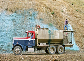
Figure 5-93 | Hydraulic seeder
The hydraulic seeder is composed of a tank that holds and mixes a slurry, and a pump system that moves the slurry through a nozzle for application to the soil surface. Photo credit: David Steinfeld
Hydroseeding equipment is composed of a tank that holds a slurry of water, seeds, soil amendments, and stabilizing products; paddles or agitation jets in the tank to mix the slurry; a high-pressure pumping system; and a hose and nozzle (Figure 5-93).
Tanks come in a variety of sizes, from a few hundred gallons to more than 3,000 gallons. As the size of the tank increases, the speed and efficiency of the operation improve. Because the travel time is the same for any size hydroseeding unit, the farther the water source is from the project site, the more efficient larger tanks become.
The hydroseeding tank is analogous to a large mixing bowl filled with various ingredients and blended together with water to make a slurry. Typical hydroseeding ingredients fall into these categories:
- Seed
- Hydraulic mulch
- Tackifier
- Fertilizer
- Soil amendments
- Dye (typically in the hydraulic mulch)
The mixture of ingredients is called a slurry. When a slurry is applied to an acre, it is referred to as a slurry unit. The quantity of each material added to a slurry tank is only limited by the ability of the mixture to be pumped through a hose and shot through a small nozzle without clogging. The tank can only hold so much material before the mixture becomes too thick to pump. Finding the right mix and rates of ingredients is important for efficient use of the equipment he applicators and manufacturers of these products can recommend optimum product rates.
For the Designer
Typically a 2 step method is sued to hydroseed with native species. A first pass is conducted with seed and water and a second pass with hydromulch.
Uniform seed coverage can be achieved by thoroughly blending hydroseeding ingredients prior to application. The two types of hydroseeding mixing systems are those that mechanically stir and those that mix using a hydraulic jet. The first system employs rotating paddles to blend the slurry in the tank and a centrifugal pump or positive displacement gear pump for slurry delivery. The second system uses a centrifugal pump to both agitate the slurry and deliver the slurry to the site. However, there is anecdotal evidence that these centrifugal pumps might be more likely to damage seed. It is suggested that designers discuss the type of hydroseeder mixing system that a contractor might use and perhaps adjust seed mixes to account for the potential increased seed damage in a centrifugal pump.
For the Designer
Many factors such as slope, soil characteristics and solar exposure help to inform the hydroseeding and hydromulching approach.
During application, the slurry is pumped to the nozzle for application. The applicator has a choice of nozzles, use of which depends on the site and slurry conditions. Slurry application can be from a “gun” mounted on the top of the hydroseeding unit or from a hose pulled manually to the application site. Stationary application (using a hydroseeding gun) is accomplished where the hydroseeding equipment can easily access the site. These areas are typically cut and fill slopes. Depending on the consistency of the slurry, the pumping system, and wind conditions, slurry can be shot 200 feet or more. Hoses are laid out for sites that cannot be reached this way. Depending on the diameter of the hose and the pumping system, hoses can reach sites more than 300 feet from the hydroseeding unit.
Hydroseeding is used when other seeding methods are impractical (Section 5.4.1). Typically, these are steeper sites where ground--based seeders are limited. Hydroseeding has the advantage over other seeding methods of applying soil amendments, fertilizers (with non-native species), soil stabilizers, and seeds together in a multi-step application. In addition, seeds that are used in hydroseeding operations do not have to be as clean (that is, free of straw, awns, chaff) as for other seeding methods. This can reduce the cost and time associated with seed-cleaning operations.
The time it takes to hydroseed is a function of the size of the mixing tank, the proximity of a suitable water source and the amount of hydraulic mulch that is applied on a per acre basis (Figure 5-94). The amount of hydromulch applied varies with aridity, slope, and soil characteristics of a given site. The greater the amount of hydraulic mulch applied per acre, the longer it will take. For example, it takes almost twice as long to apply 2,000 lb/ac of hydraulic mulch through hydroseeding equipment as it does to apply 1,200 lb/ac. For this reason, determining the appropriate amount of hydraulic mulch is important from a cost standpoint. Cost includes not only the cost of purchasing the product, but also the time to apply it. Tank size is also an important factor in application rates; the larger the tank, the less application time it takes. A 3,000-gallon mixing tank, for example, takes less than half the time to cover an acre than a 1,000-gallon tank.
Hydroseeding in wildland revegetation has a number of limitations (Stevens and Monsen 2004) that may have relevance in roadside revegetation for pollinators:
- Some seeds may not be placed in the soil depending on application method
- Seeds and seedlings can dry out
- Some seedlings cannot grow through paper fiber type of hydraulic mulch
- Seeds can be damaged by agitators and pumps
- Precocious germination can occur as a result of moisture in the hydraulic mulch
- Hydroseeding requires large quantities of water
With good planning, implementation, and monitoring, many of these limitations can be managed, resulting in successful revegetation. Ultimately, the success of any hydroseeding project comes down to the availability of water during germination and seedling establishment. As with other seeding methods the timing of hydroseeding application is determined in part by the climate at a project site. Hydroseeding is successful in the landscaping business because seeds are irrigated after hydroseeding until a stand of grass has become established. One applicator stated, “what people don’t understand is you can do the best hydroseeding job in the world but if they don’t water it, it’s not going to grow” (Brzozowski 2004). The challenge in roadside revegetation is that, for most projects, irrigation is not available. To make hydroseeding successful, strategies that maintain moisture around the seeds and in the soil during early plant establishment are usually most effective.
Integrate Hydroseeding into Revegetation Strategy
From a revegetation standpoint, hydroseeding serves as a method of seed placement, a means of stabilizing the soil surface for controlling erosion and to allow seedlings to become established, and a way to apply fertilizers and other soil amendments. These objectives cannot always be met in one hydroseeding operation. It often requires that each objective be considered independently and then integrated into an overall strategy. Clarifying objectives, based on the site-specific conditions of the project, and determining the best way to achieve them using hydroseeding equipment as part of the approach will lead to the best revegetation results. For example, seed placement and fertilizing are different objectives, yet meeting both objectives is often accomplished in one hydroseeding operation out of convenience. However, the best time to apply fertilizers on many projects is after the seeds have germinated (Section 5.2.1). Instead of meeting fertilizer and seeding objectives in one hydroseeding operation, separating them into two different applications would be a better strategy for meeting overall project objectives.
On a site with high surface rock, for example, the main objective would be seed placement. Little importance would be placed on surface stabilization because the rock has already created a stable surface. The best potential sites for seedling germination on this harsh surface would be between the surface coarse fragments where seeds are protected and moisture collects. Yet a common mistake that occurs in many hydroseeding projects is to include the same rates of tackifiers as would be used on a soil surface. Under these circumstances, tackifiers adhere seeds to the rock surface, preventing the seeds from washing between the gravel and cobbles that cover the surface. The objective of stabilizing the surface is not only unnecessary in this example, it would negatively affect placement of seeds.
It is good practice to accomplish hydroseeding within a strategy of creating an optimum seed environment. The hydroseeding operation places seeds on the surface of the soil, which is often a poor environment for germination. Hydraulic mulch is inferior to long-fiber mulches in reducing surface temperatures, maintaining soil moisture, and moderating surface temperatures, especially in more arid climates (Section 5.2.3). The term “hydraulic mulch” is misleading because some materials that fall into this category like paper fiber mulch, lack many of the important properties associated with mulches (Section 5.4.2, see Select Hydraulic Mulch and Determine Rates). By their nature, hydraulic mulches are more like a growing medium than mulches because of their capacity to absorb water (most hydraulic mulches hold greater than 1,000 times their weight in water). As a growing medium, hydraulic mulch maintains high moisture around the germinating seeds, but once the hydraulic mulch dries out, which is often very quickly on dry sites, it no longer protects the seeds from drying as a mulch would and germination rates are compromised.
The literature is scant and inconclusive on the benefits of hydraulic mulch to seed germination and seedling establishment in wildland conditions. Carr and Ballard (1980) found no difference in plant establishment when seeds were applied with and without hydraulic mulches, but only low rates of hydromulches were compared. One approach to increasing seed germination that is often used in drying climates is a two-pass application system where seeds and a minimum amount of hydraulic mulch are applied in the first pass, and then covered by a thick application of hydraulic mulch in a second pass. While this application method appears to have some advantage over a one-pass operation because the seeds are covered with a greater thickness of hydraulic mulch, it is not known what the difference in germination and seedling establishment rates might be. The benefits from a germination standpoint are probably not seen until the hydromulch rates are high (3,000 lb/ac or greater). Even then, on arid sites receiving less than 6 inches precipitation, higher hydraulic mulch rates can intercept the low amount of precipitation that is received, preventing moisture from reaching the seeds (Section 3.8.1, see Rainfall Interception). Because it is uncertain whether hydraulic mulches improve germination, it is better to base mulch rates on surface stability objectives than on seeding objectives and use other methods to improve seed germination. For example, it might be more effective to reduce the amount of hydraulic mulch to the minimum amount necessary to apply seeds and, with the costs savings, apply a long- fibered mulch in a second operation.
Identify Hydroseeding Areas
Hydroseeding typically takes place after the final slope shaping and topsoil placement have been completed. Several months before hydroseeding is to occur, the site can be visited to finalize an implementation plan that includes the locations of where the plants or cuttings are to be installed and where seeding will take place. While most of the hydroseeding areas will conform to the revegetation units developed during planning, the site always looks different after construction. In this field review, the exact locations of the areas that will be hydroseeded are drawn on a road map and areas are identified where different seed mixes, fertilizer types/rates, or hydraulic mulch rates will be applied.
The acreage for each hydroseeding area is calculated using methods described in Table 5-1. This method partitions the cut and fill slopes into rectilinear units by road stations and calculates acreage between each unit. This information is then summarized in a hydroseeding table (shown in Inset 5-21) that is used to develop task orders. It can also be used in the field for keeping a record of acreages and the location of hydroseeding operations.
The proximity to streams is one consideration when locating hydroseeding areas. If hydroseeding areas are adjacent to ditches or waterways that drain into live streams, a buffer can be included around these features to avoid fertilizers entering the stream system. Fertilizers applied to these sites have the potential of entering ditches during rainstorms and eventually reaching a stream course as nutrient pollution. Road runoff can be a significant contributor of nutrients to water systems (Reuter et al 1998).
Determine Seeding Rates
Sowing rates for hydroseeding are calculated using the same method outlined in Figure 5-92. The designer is referred to this section for determining seeding rates for any type of sowing method. These sowing calculations assume that the method of sowing does not damage the seeds. This might not be a good assumption with hydroseeding, which has been shown to increase the risk of seed breakage in the hydraulic seeder tank during mixing (Kay et al 1977; Wolf et al 1984; Pill and Nesnow 1999). Additions of fertilizers further increase the risk by exposing seeds to high salt levels when seeds are in the slurry tank and also after they are applied to the soil surface (Brooks and Blaser 1964; Carr and Ballard 1979; Brown et al 1983). Taking precautions to reduce the risk of seed damage during hydroseeding will increase the seed germination rates and reduce the amount of seed needed for the project.
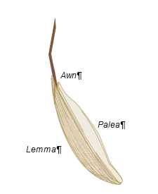
Figure 5-95 | Grass seed morphology
Grass seeds are protected by sets of bracts called the lemma and the palea (the lemma is the larger, outer covering, and the palea is the shorter, interior sheath). The awn is a fibrous bristle that extends from the midrib of the lemma. The awns for most grass species are removed during cleaning for easy sowing. It is good practice to keep the lemma and palea on the seeds to protect them from seed damage during sowing, especially in hydroseeding operations.
Considerations that can reduce the risk of damaging seeds include the following:
- Type of hydraulic seeder
- Seed condition
- Duration in slurry
- Seed moisture
- Hydraulic mulch
- Nozzle and nozzle position
- Fertilizers
Hydraulic Seeders—Hydraulic seeders that use centrifugal pumps for agitation and delivery can have a higher potential to damage seeds than systems with paddles and rubber-coated gear pumps (Kay 1972a; Kay et al 1977). Kay (1972a) found that germination of intermediate wheatgrass (Agropyron trichophorum) seeds was reduced from 80 percent (control) to 10 percent germination after one hour in a centrifugal agitation system; after two hours, germination was reduced to 1 percent. There was no reduction in germination after one hour using paddle agitation, but germination declined to 59 percent after two hours. Pill and Nesnow (1999), however, found that centrifugal pumps did not reduce germination rates of Kentucky bluegrass (Poa pratensis) and perennial ryegrass (Lolium perenne) after mixing for an hour in a slurry tank.
Seed Condition—Grass seeds are enclosed by sets of bracts, called the lemma and palea. These structures provide a protective covering (Figure 5-95) and are believed to reduce seed breakage during hydroseeding agitation and application. In the aforementioned study, Pill and Nesnow (1999) believed that one of the primary reasons there was no decline in germination after an hour of mixing in a slurry tank was because the lemmas and paleas were still intact around the seeds. The association between presence of these seed structures and protection from seed breakage during hydroseeding is one thing to consider when cleaning seeds for hydroseeding. Seed cleaning is necessary for storage and seeding (Section 5.3.1 and Section 5.3.4). However, seeds for use in hydroseeding operations do not have to be as clean as seeds used in other seeding methods. Each species has different cleaning requirements for hydroseeding. Some need thorough cleaning, while others might require very little cleaning. It would be beneficial to discuss the level of seed cleaning for hydroseeding with seed extractory personnel and seed increase contractors.
Duration in Slurry—The longer seeds are mixed in the slurry tank, the greater the potential for breakage. Kay et al (1977) found that after 20 minutes of agitation, seed germination decreased significantly for Bermudagrass (Cynodon dactylon) (Figure 5-96). For this reason, it is important to add seeds immediately before application.
Seed Moisture—As a general rule, moistened seeds have less potential for breakage than dry seeds because they are more flexible when impacted. Kay et al (1977) found that soaking Bermudagrass seeds for 1.5 days prior to application significantly increased germination over dry seeds (Figure 5-96). Longer soaking periods (4 days) had negative effects on germination because radicles were emerging and were damaged with mixing.
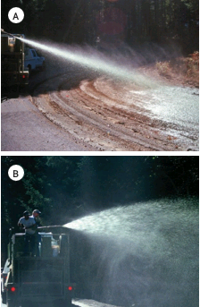
Figure 5-97 | Hydraulic seeder nozzles
Hydraulic seeders are equipped with several types of nozzles. The nozzle shown in Photograph A shoots long, high pressure, streams, while the fan nozzle shown in Photograph B spreads the slurry out for closer applications. Photo credit: David Steinfeld
Soaking seeds prior to hydroseeding will unfortunately initiate seed germination, which is not usually desirable for hydroseeding projects. Pill and Nesnow (1999) suggest seed priming as an alternative to soaking. Priming is a seed treatment that partially moistens seeds without initiating seed germination (Pill et al 1997). Seed is mixed at 1 part seed to 10 parts moist vermiculite (although peat could be used as a substitute) and stored at cool temperatures for up to 10 days prior to hydroseeding.
Hydraulic Mulch—Hydroseeding without hydraulic mulch can increase seed damage (Kay 1972a, 1978). Using a minimum rate of 500 lb/ac hydraulic mulch is suggested for protecting seeds (Kay 1978).
Nozzle Type and Nozzle Position—Shooting slurry straight at the soil in close range can damage seeds. The impact at high speeds can cause seed coats to break. As one hydroseeding operator describes the action, “we just shove that seed right smack in the ground with a lot of force…the gun was slamming straight to it” (Brzozowski 2003). Describing this action to a Forest Service seed extractory specialist, his reaction was, “that can’t be good for the seed” (Barnar 2007). In the seed production and seed extraction businesses, handling seeds carefully is a high priority. This attitude and practice does not stop with the seed producers, but follows through to the application of seeds. One application practice that could reduce seed damage is to aim nozzles so the slurry is not hitting the soil surface with full force at close range. Arching the slurry stream so the spray hits with lower force is more desirable. Using less pressure or lower pressure nozzles, such as fan nozzles, can also reduce seed damage (Figure 5-97). Some soils are very loose or powdery after construction, which can cushion the seeds, as opposed to very compacted surfaces. Seeds applied to these surfaces can be buried under the loose soil when the slurry is shot straight at the surface, offsetting the effects of seed breakage and increasing germination potential (Mast 2007).
Fertilizers—Adding fertilizer to the slurry can reduce germination of certain species due to the effects of fertilizer salts on seed imbibition, or uptake of water (Figure 5-98) (Brooks and Blaser 1964; Carr and Ballard 1979; Brown et al 1983). This is not just a problem when seeds and fertilizers are mixed together in the slurry tank; it can also negatively impact the seeds after they are applied to the soil surface and before the first rains dilute the surrounding salts. Effects of fertilizer salts are more detrimental on sites with low rainfall. Carr and Ballard (1979) found white clover (Trifolium repens) and, to a lesser degree, Festuca spp. had the greatest reduction in germination (Figure 5-6). They suggest white clover be applied by hand, separate from the hydroseeding operation.
Assuming that most native seeds, especially legume species, are affected by fertilizer salts, it is important to understand what the effects of different types and rates of fertilizers will have on the salt concentrations in the slurry. Brooks and Blaser (1964), Carr and Ballard (1979). And Brown et al (1983) used inorganic, fast release fertilizers, which dissolve quickly in solution (Section 5.2.1). Organic and control release fertilizers, however, dissolve slowly and therefore typically have lower salt levels in solution. Whichever fertilizers or rates are used, tests of the slurry for soluble salts can be conducted to ensure that concentrations are not lethal (Section 3.8.4).
The effect of hydroseeding operations on seed viability is an important issue and deserves more research attention. Monitoring information can be used to broaden understanding on how to properly use this important tool.
Select Hydraulic Mulch and Determine Rates
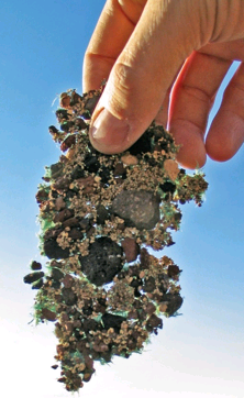
Figure 5-99 | Hydromulch as a bonded fiber matrix
Hydraulic mulch applied at high rates and with specialized tackifiers will hold together as a sheet and is referred to as a "bonded fiber matrix," or BFM. The application rate of wood fiber mulch in this picture was 3,000 lb/ac. Photo credit: David Steinfeld
Hydraulic mulch is a low bulk density material applied through a hydraulic seeder to increase surface soil strength and reduce erosion. At high application rates, seeds are covered, thereby increasing the potential for increased seed germination. Commercial hydraulic mulches are derived from wood fiber, recycled paper (wood cellulose), sterilized grass straw synthetic fibers, mechanically treated wood fibers, or combinations of these. Wood fiber mulches are manufactured from wood chips thermally treated by a steam and high pressure shredding process; wood cellulose mulches are made from waste paper materials such as recycled newspaper and cardboard (Trotti 2000). Hydraulic mulches typically have very high water-holding capacities (over a 1,000 times their weight in water). A pound of wood fiber mulch, for example, absorbs between 1.5 to 2.5 gallons of water and, inversely, a gallon of water holds between 0.40 and 0.66 pound hydraulic mulch. This is important information to know when determining how much hydraulic mulch to add to a slurry tank. Most operators will not exceed a ratio of 0.4 to ensure they do not clog their system with a slurry that is too thick. At this proportion, a 1,000-gallon tank would hold 400 pounds of wood fiber mulch. Product specification sheets typically indicate the ratio of hydraulic mulch to water for hydroseeding equipment.
The depth and cover of hydraulic mulch depends primarily on the quantity and properties of the mulch placed in the tank. Typical hydroseeding mulch manufacturer’s application rates range in application rates from 1,000 to 3,000 lb/ac. At lower application rates (<1,000 lb/ac), wood cellulose (paper) fiber mulch will not cover the entire soil surface, leaving most seeds and much of the soil surface exposed. At the manufacturer’s recommended application rates or higher (>3,000 lb/ac) the soil surface and seeds are usually completely covered (Figure 5-99). A class of higher strength mulches, purposefully manufactured with the tackifiers and tracer dye, called bonded fiber matrixes (BFM) are applied at rates above 3,000 lb/ac. Correctly applied this BFM can bond together to form a continuous mat given that fiber length is typically longer in these products. A BFM will stabilize seeds and control surface erosion up to a year after application depending on site conditions. Even more robust than BFM, High Performance Growth Media (HPGM) consists of engineered and mechanically kinked fibers that interlink when applied to soil. When applied correctly, sprayed from two different directions at the specified application rate, and achieving complete coverage, the HPGM becomes, in effect, a hydraulically applied erosion control matting as well as a growth media for seeds. Correctly applied wood fiber HPGM has a functional life of about a year and a coconut fiber HPGM has a functional life of two years although fiber longevity will vary by site specific characteristics such as soil type or canopy cover.
The length of the wood or cellulose fibers is an important characteristic in creating a soil cover mulch that does not restrict seed germination or plant growth. Cellulose mulches have shorter fibers than wood fiber mulches and, therefore, these materials compact much easier when they are applied. Applying too much cellulose mulch can result in a soil surface that has the consistency of “paper mache.” At application rates greater than 1,500 lb/ac cellulose mulch, there is a reduction in infiltration and air exchange, and seed germination and seedling establishment are decreased (Gassman 2001). Some manufacturers have overcome this problem by mixing straw, a long-fibered material, with paper mulch. Typically, cellulose mulch requires 20 to 40 percent more material to achieve the same uniformity of coverage as wood fiber mulch (Trotti 2000) (Figure 5-100). While recycled paper mulches are typically less expensive than wood fiber, the cost savings are partially offset by the increased amount of paper mulch used. Blended mulches (those with equal portions of wood fiber with recycled paper) are an effort to improve the characteristics of recycled paper by adding wood fiber.
Typically, paper a fiber or cellulose fiber mulches are the lightest duty mulches which are best used on flat or gently sloping surfaces. It is usually best to apply this mulch at the manufacturer’s recommended application rate (1,000-2,000 lb/ac). This mulch has issues in that it provides little in the way of erosion control, it can form a paper mache-like crust that some seeds cannot penetrate and it lays down in a dense layer with little pore space which when dry can wick moisture from the soil. Wood fiber and straw derived hydromulches provide little in the way of erosion control and are most effective when used on gently sloping surfaces. These mulches are installed at a manufacturer’s recommended application rate of about 2,000 lb/ac. When correctly installed they have enough loft to allow seedlings to penetrate through the mulch. They hold some moisture which aids germination but provide little in the way of thermal regulation of the soil. The BFM and high performance growth media (HPGM) are manufactured to have long and short fibers that are mechanically treated so that they interlink with open pore space, when applied at the recommended application rate, which can be as high as 4,500 lb/ac. These products are generally packaged with tackifier and tracer dye for accurate use. They can provide excellent erosion control and can be used on slopes of 1:1 or steeper. It is recommended that these materials be used in a multi-step process with the seed and minimal mulch be sprayed on in the first pass, then the rest of the mulch cover the seed in two following passes from different directions so that the seed is in good contact with the soil and the mulch forms a contiguous layer covering the seed. These materials have good loft allowing seedling penetration, they have enough thickness to hold moisture help retain soil moisture and they provide a small measure of thermal regulation to the soil. BFMs and high performance growth media are the most expensive of the hydraulically applied mulches.
The use of hydraulic mulch for seed germination becomes less important on wetter sites, especially in climates where there is little soil drying during germination (Carr and Ballard 1980). These conditions are found from fall through early spring on many sites in the Coast Range and Cascade Mountains, as well as microsites that include north aspects and sites shaded by vegetation. On these sites, 1,000 lb/ac or less might be sufficient for seed germination, giving deference to manufacturer’s recommended application rates. In areas with high rainfall and erosive soils, a higher strength hydraulic mulch at higher application rates or even a bonded fiber matrix might be needed to keep seeds and soil in place until seeds have germinated and grown into established seedlings.
Select Tackifier
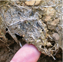
Figure 5-101 | Hydraulic mulch and tackifiers
Hydraulic mulch with tackifiers remains effective for up to a year. This hydraulic mulch and tackifier slurry was applied nine months prior to this picture and was still partially effective. Photo credit: David Steinfeld
Tackifiers are sticking agents that bind soil particles together and protect the surface from wind and water erosion. When applied with hydraulic mulch, tackifiers increase the effectiveness of the mulch as a soil cover by binding the hydraulic mulch fibers and the surface soil particles together. Tackifiers create water-stable surfaces, which means they are capable of repeated wetting and drying and do not lose strength after a series of rainstorms. Hydraulic mulch and tackifiers can remain effective even through a winter with high precipitation (Figure 5-101).
Selecting a tackifier can be difficult. Numerous commercially available products are on the market from which to choose. Unless these products have been used side by side in the field, it is difficult to know the difference among them. A hydraulic seeder operator can offer advice on tackifiers and other hydraulic seeding products because they have tried a variety of products and usually have a good idea of their effectiveness. Many mulches are pre-packaged with the appropriate ratio of tackifier.
The two general types of tackifiers commonly used in hydroseeding are organic and synthetic. Organic tackifiers are derived from plant materials, which include guar, plantago, and other plant starches. Synthetic tackifiers are manufactured polymers and copolymers that include polyacrylamides (PAM), acrylic polymers and copolymers, methacrylates and acrylates, and hydro-colloid polymers. Organic tackifiers break down biologically and are typically effective for at least three months depending on site conditions and product type. Synthetic tackifiers are photo and chemically degradable and have somewhat greater longevity than organic tackifiers, lasting up to a year on many sites (CASQA 2003b).
Revegetation specialists and operators usually develop a preference for tackifier products based on ease of handling and storage, ease of application, toxicity to plants, environmental concerns, weather restrictions, and application rates.
Handling and Storage—Tackifiers are available as dry powder or liquid formulations. Most organic and some synthetic tackifiers are packaged as dry powders. These products are easy to handle and store because they weigh less and have less bulk than liquid containers. Liquid tackifiers are best stored in areas that will not freeze if stored over the winter. Handling and disposal of plastic containers are also a consideration when using liquid tackifiers.
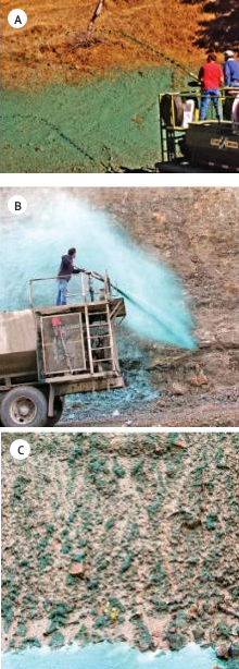
Figure 5-102 | High viscosity tackifiers
High viscosity tackifiers, mixed at manufacturer recommended rates, keep the slurry together during application using a “stream” nozzle (A). Low viscosity tackifiers, or slurries with low concentrations of tackifiers, do not hold together when applied and will drift with wind (B) or run off slopes (C). Photo credit: David Steinfeld
Ease of Application—An important property of tackifiers is viscosity. Viscosity is the measure of the “stickiness” of a tackifier, or the propensity of the tackifier to hold a slurry together when it is applied. Tackifiers with high viscosity, such as guar-based tackifiers, will hold the slurry together as a fine stream when pumped from the nozzle (Figure 5-102A), and the stream of slurry will shoot farther. When a slurry with high viscosity hits the soil surface, it sticks and does not easily run off. A slurry with low viscosity, however, will separate as it is comes out of the nozzle and drift, especially if there is a breeze, resulting in uneven application (Figure 5-102B). If low viscosity slurries are applied at rates that are greater than the soil infiltration rates, the slurry will run off the surface. Not only will seeds be lost, but other materials in the slurry (including fertilizers) could enter surface drainage systems (Figure 5-102C).
Tackifiers act as lubricants and create less friction through the hydraulic equipment. With high viscosity tackifiers, equipment runs smoother and nozzles do not plug as frequently. This will enhance the overall performance and longevity of the equipment.
Toxicity to Plants—One reason organic tackifiers are sometimes preferred over synthetic tackifiers is the belief that these materials are better for seed germination and seedling establishment. They are organic substances that break down into non-toxic compounds. While organic tackifiers are sometimes advertised as being better for plant health, there is nothing in the scientific literature to indicate that synthetic tackifiers are any more harmful or toxic to plant establishment than organic tackifiers.
Environmental Concerns—There have been concerns about the use of polyacrylamides (PAM) on human health and the environment. Acrylamide, a known neurotoxin to humans, is the main ingredient of this polymer. Polyacrylamides alone have low toxicity—LD50 of 5,000/kg oral dosage (Peterson 2002). However, in the manufacturing of the polymer, some acrylamide is formed. While PAM does not appear to break down in the environment to acrylamide if released during decomposition, it is thought to be quickly decomposed by soil microbes (Peterson 2002). Furthermore, because PAM degrades slowly in the environment, there should not be an accumulation of acrylamide in the soil (Claassen and Hogan 1998). Evans (2006) cites reviews by Barvenic (1994) on health hazards and Goodrich et al (1991) on aquatic macrofauna, edaphic microorganisms, or crop species. When polyacrylamides were applied at recommended rates, the materials were found to be safe for the environment. The designer is referred to Barvenik (1994) for a comprehensive discussion of PAM in the environment.
As with all products used in revegetation, it is good practice to request a Material Safety Data Sheet from the manufacturer of the product and reviewed for possible human effects and effects to the environment. Some states have regulations on the use of synthetic polymers in landscaping. It is important to be abreast of the latest environmental regulations (Peterson 2002).
Weather Conditions—Tackifiers have limitations and conditions for proper application, including the fact that soils are best moistened prior to application; a 1- to 3-day drying period is typically necessary after application; the site cannot freeze during or immediately after application; or they are to be applied between a certain temperature range. It is important to understand which environmental restrictions apply to the tackifier being used and how it might affect the hydroseeding operations. A site that is expected to be wet in the fall, for example, will likely require a tackifier that needs a minimal curing period.
Tackifier Rates—When tackifiers are used with hydraulic mulches, they are applied at rates at 5 to 10 percent of the weight of the hydraulic mulch (CASQA 2003a). Refer to manufacturer labels for specific rates.
Select Other Slurry Components
The remaining components of the hydroseeding slurry can include dyes, fertilizers, biostimulants, and mycorrhizae.
Dyes—Dyes are used as markers for the applicator to indicate where the slurry has been applied. Most hydraulic mulches include dyes, so it is not usually necessary to include dyes in the slurry when using these mulches.
Fertilizers—Fertilizers are often applied through hydroseeders. Determining the type and amount of fertilizers to use is discussed in Section 5.2.1.
Biostimulants—Biostimulants are sometimes applied to the slurry.
Mycorrhizae—Mycorrhizae are often included in the slurry (Section 5.2.7).
Locate Water Source
Hydroseeding cannot be conducted without a water source, yet a common mistake is to wait until the last minute to locate such a source. For many parts of the western United States, water sources can be long distances from the project site. It is important to establish where water will be obtained for hydroseeding early in the planning process. Considerations when selecting a water source include the following:
- Distance—On projects where the water source is a long distance from the hydroseeding site, large slurry tanks will increase the efficiency of the operation. Conservation of water is a priority in these circumstances. Covering more area with each slurry tank is one way to reduce water needs. This can be accomplished by applying lower rates of hydraulic mulch and tackifier per acre.
- Water quality—Water for hydroseeding is best when it is low in salts and other potentially toxic compounds. If in doubt, send a sample to a water quality lab for testing or, at minimum, run pH and conductivity measurements on a sample.
- Water use permits—Always check with the agency or landowner for permits to use their water.
Develop Hydroseeding Contract
Once a basic hydroseeding plan is developed, a contract is developed. The contract usually contains most of the following elements:
- Site location and description—A general description of the site, slope gradients, location, and time of year the hydroseeding will occur are topics that are typically addressed.
- Products and rates—The hydroseeding products or equivalent products (hydraulic mulch, tackifiers, fertilizers, etc.) are identified, and the rates per acre for each product are stated for each hydroseeding mix or mixes. The total number of acres for each hydroseeding mix can be tabulated.
- Water source—The location and distance to each water source are described. The contract typically indicates whether it is the responsibility of the contractor to obtain agreements from owners for use or any required water permits.
- Storage area—The contractor will need a site to store hydraulic mulches, tackifiers, fertilizers, and other materials associated with the hydroseeding operation. Effective sites are usually in close proximity to the hydroseeding areas and relatively safe from vandalism.
- Equipment—If specific types of hydraulic seeders are required for the job (large tank, or tracked equipment for example), it is important to specify them in the contract. Using hoses to access portions of the project site will often be necessary. The contract can specify how many feet of hose are needed and what percentage of the project will be applied by hose.
- Cleaning equipment—The contract can state that the tank and hoses will be cleaned from all previous hydroseeding or hydromulching projects. The equipment will be inspected and, if it does not pass inspection, the contractor can be required to clean equipment at an approved offsite location.
- Weather conditions—The weather conditions, based on manufacturer specifications, are other factors that can be stated. The contract can specify acceptable temperature ranges and wind velocities. It can also state whether rain or freezing temperatures can occur within a specified period after application. A provision could be stated that applications will not occur on frozen ground. Some tackifiers also require that soils be moistened before application.
- Mixing—The contract can state that the seeds be mixed into the slurry immediately before application. It could also further state that the slurry be applied within 30 minutes after the seeds have been placed in the tank. When the seeds are in the slurry, good practice is to moderately agitate the slurry only enough to mix the seeds and keep it from separating.
- Application—The slurry is most effective when applied at the manufacturers recommended application rate. Anything less than 100 percent coverage of the soil surface is incorrect application of the material. Slurry works best when it does not run off the soil. If it does, adjustments to application speeds or nozzles can help. (Figure 5-97 and Figure 5-98 show the spray pattern of two types of nozzles.) It is good practice to avoid applying slurry at a range that causes slurry to splash off the surface and soil to dislodge. A two-pass method is preferred to obtain good seed coverage. In the first pass, 50 percent or less of the slurry is applied, followed by the second pass that applies the remainder of the material. Each pass is applied in a different direction (bidirectionally), which reduces the “shadow effect” created by just one pass and may serve to better lock the matrix together (Bill Mast personal communication).
- Traffic control—The contract can state how traffic safety will be ensured during application. Will the contractor be required to supply signs, warning lights, or flaggers?
Keep Good Records
Hydroseeding is a complex task. Not only are several products being applied at different rates at one time, but they are also typically being evenly applied over large complex areas. A skilled hydroseeding operator at the helm can help ensure success, and it is important to keep track of what is being applied and the acres on which it is being applied. This will ensure that the target amount is being applied and enable accurate payment to the contractor.
The records begin with the original hydroseeding prescription. These are the planned application rates of each hydroseeding material. It is not enough to know what is wanted as a finished product on the site; understanding how it will be accomplished is also important. This means that the prescribed product quantities per acre are translated into how it will actually be applied. These calculations can be challenging, especially when the hydroseeding operation is in full swing. It is better to have some idea how this will work before arriving in the field. Inset 5-21 provides a guide through the process of determining how much of each hydroseeding material should go into a slurry tank. These calculations, along with the contract specification, become the operation plans.
During hydroseeding operations, it is helpful for the contract inspector to keep track of each slurry tank that is applied. This includes the time, amount of water, quantities of products, location, acreage, and weather conditions. Calculating the acreage of each slurry tank is important in the field to ensure that the rates of materials are being applied as prescribed. This can be accomplished using a method shown in Inset 5-21, Table 4.
When this information is collected, the actual applied rates of materials per acre can be made using the method shown in Inset 5-21, Table 6. This will show how close each slurry tank came to the prescribed rates. This is important feedback for the hydroseeder operator. If the application rates were off significantly, adjustments can be made quickly. These records can be summarized at the end of the project to determine total quantity of materials used and the number of acres covered. This information can be the basis for contract payment.
On projects with significant earthwork, cut or fill slopes can be longer than the distance a hydroseed spray can reach. Plan seed applications so that exposed soils are seeded while they are accessible. This may require multiple visits by the hydroseeding contractor.
Inset 5-21 | Keeping track of the numbers
Hydroseeding might look easy, but keeping track of the numbers is not. Most hydroseeding operators have learned to make calculations in their heads on the run. However, unless this type of work is conducted frequently, the designer will not be able to manage this along with the other requirements of being a contract inspector. As fast as this operation goes in the field, a good record-keeping system is essential. After all, it is the designer’s responsibility to ensure that the contract is being fulfilled.
Planned Application Rates. A hydroseeding plan is developed during the preparation of the contract that locates hydroseeding areas and defines general rates of materials to be applied. Table 1 shows how planning information for hydroseeding can be displayed. In this example, three hydroseeding mixes are defined by different rates of tackifier, mulch, and seed mixes in a slurry unit. Hydro mix 1 will be applied on gentle slopes requiring only a light covering of mulch at 1,000 lb/ac. Hydro mix 2 is for steeper slopes and requires 2,000 lb/ac mulch and more tackifier. Hydro mix 3 is for very erosive slopes and requires 3,000 lb/ac mulch and a different seed mix. The hydro mix locations are designated on a road map. From this table, a total quantities list of materials for the project can be made by multiplying the per acre rates by the acres for each hydro mix.
Table 1 Slurry Unit (per Acre Rates)
| |
|
|
|
Seed |
Tackifier |
Mulch |
Fertilizer |
| Hydro Mix |
Reveg Units |
Seedmix |
Acres |
Bags/ ac |
Buckets/ ac |
Bales/ac |
Bags/ac |
| 1 |
A2, B1 |
A |
2.0 |
4 |
100 |
1,000 |
1,000 |
| 2 |
B1 |
A |
5.0 |
4 |
200 |
2,000 |
1,000 |
| 3 |
D1, D2 |
B |
3.5 |
4 |
200 |
3,000 |
1,000 |
| Total quantities |
1,900 |
22,500 |
10,500 |
Conversions to Product Units. When in the field, it is best to avoid thinking in terms of pounds per acre because every product comes in packages. For example, mulch may be packaged in 45 pound bales. To simplify things, converting all rates from pounds per acre to product units can be helpful (Table 2).
Table 2 |
Tackifier |
Mulch |
Fertilizer |
Pounds per |
50 |
45 |
50 |
Product unit |
Bucket |
Bale |
Bags |
Operational Plans. Table 3 converts the planned application rates to operational loading rates by converting “pounds per acre” to “product units per acre” and converting “product units per acre” to “product units per slurry tank.” The key to these calculations is knowing approximately how many acres each slurry tank will cover. This is a function of the size of the slurry tank and the amount and type of mulch and other materials being mixed in each tank (Section 5.4.2, see Select Hydraulic Mulch and Determine Rates) for calculating acres per slurry tank). In this example, it was estimated that hydro mix 1 would cover approximately 1.5 acres. Hydro mix 2 would cover one-half the area (0.75 ac) because twice the hydromulch is being applied. Hydro mix 3 would cover one-third of the area as hydro mix 1. The math, using tackifier in hydro mix 1 as an example, is 100 (Table 1 grey cell) / 50 (Table 2 grey cell) * 1.5 (Table 3 grey cell) = 3 (Table 3 gold cell) buckets per slurry tank. Notice the difference in some of the product unit rates, such as the fertilizer.
Table 3 Per Slurry Tank
|
|
|
|
Seed |
Tackifier |
Mulch |
Fertilizer |
Hydro Mix |
Tank Size |
Ac/Tank |
Seed- mix |
Bags |
Buckets |
Bales |
Bags |
1 |
3,300 |
15 |
A |
6 |
3 |
33 |
30 |
2 |
3,300 |
0.75 |
A |
3 |
3 |
33 |
15 |
3 |
3,300 |
0.5 |
B |
2 |
2.0 |
33 |
10 |
Operations Diary. Table 4 covers the minimum amount of information to be collected during hydroseeding operations. It captures date, time, and quantity of product units placed in the slurry tank. It is also a record of the acres that were covered by each slurry tank (refer to Table 7 for a quick way to determine acreage). Notice that the application rates in this example (ac/tank) were variable, especially for Tank 2. This is not uncommon for hydroseeding projects. At the end of each day, Table 4 is used to summarize the amount of materials used and to track inventory. This table is the basis for contract payment.
Table 4
|
|
|
|
|
|
|
|
Seed |
Tackifier |
Mulch |
Fertilizer |
|
Tank |
Map |
Date |
Start |
Finish |
ac/Tank |
Water (gal) |
Seed mix |
Bags/ac |
Buckets/ac |
Bales/ac |
Bags/ac |
1 |
A2 |
10/18/07 |
9:15 |
9:50 |
1.20 |
3,300 |
Mix 1 |
6 |
2.0 |
33 |
30.0 |
2 |
A2 |
10/18/07 |
10:10 |
10:50 |
1.80 |
3,300 |
Mix 1 |
6 |
2.0 |
33 |
30.0 |
3 |
B1 |
10/18/07 |
11:20 |
11:55 |
0.70 |
3,300 |
Mix 1 |
3 |
5.0 |
33 |
15.0 |
4 |
B1 |
10/18/07 |
13:00 |
13:35 |
0.95 |
3,300 |
Mix 1 |
3 |
5.0 |
33 |
15.0 |
5 |
B1 |
10/19/07 |
14:15 |
15:15 |
0.80 |
3,300 |
Mix 1 |
3 |
5.0 |
33 |
15.0 |
Total quantities |
21 |
19 |
165 |
105 |
Actual Applied Rates. Tables 5 and 6 convert what was actually applied back to pounds per acre to compare what was originally planned from Table 1. For example, 33 bales of mulch were applied in Tank 4 (shaded cell in Table 4). It is converted to actual pounds per acre as follows:
33 * 45 (shaded cell in Table 5) * 0.95 (shaded cell in Table 6) = 1,563 lbs/ac (circled cell in Table 6)
Compared to the original plan, this was three-quarters of the planned rates because the slurry tank was applied over a greater area than originally planned. For seed rates, this means that a one-quarter fewer seeds were applied.
Table 5 |
Tackifier |
Mulch |
Fertilizer |
Pounds per |
50 |
45 |
50 |
Product unit |
Bucket |
Bale |
Bags |
Table 6
|
Seed |
Tackifier |
Mulch |
Fertilizer |
|
Tank |
Map |
Date |
Start |
Finish |
ac/Tank |
Water (gal) |
Seed mix |
Bags/ac |
Buckets/ac |
Bales/ac |
Bags/ac |
1 |
A2 |
10/18/07 |
9:15 |
9:50 |
1.20 |
3,300 |
Mix 1 |
5.0 |
83 |
1,238 |
1,250 |
2 |
A2 |
10/18/07 |
10:10 |
10:50 |
1.80 |
3,300 |
Mix 1 |
3.3 |
56 |
825 |
833 |
3 |
B1 |
10/18/07 |
11:20 |
11:55 |
0.70 |
3,300 |
Mix 1 |
4.3 |
357 |
2,121 |
1,071 |
4 |
B1 |
10/18/07 |
13:00 |
13:35 |
0.95 |
3,300 |
Mix 1 |
3.2 |
263 |
1,563 |
789 |
5 |
B1 |
10/19/07 |
14:15 |
15:15 |
0.80 |
3,300 |
Mix 1 |
3.8 |
313 |
1,856 |
938 |
Prior to hydroseeding, review the areas to be hydroseeded in the field (Table 7). For each road station (column C), the length of the slope (column D) that will be hydroseeded is measured (or estimated) and recorded. This information is placed in a spreadsheet as shown in this figure, and acreage for each station is made by multiplying slope length by distance between stations (column E) and converting to area units (columns F and G) (e.g., acres). During hydroseeding, the stations and percentage of area to be covered (column B) within the station are recorded for each slurry tank (column A). Partial station coverage is estimated and acreages adjusted, as shown in the last entry in this example. When the slurry is completed, the total acres for that slurry tank are summed.
Table 7
A |
B |
C |
D |
E |
F |
G |
|
|
Tank |
% Covered |
Station |
Slope Length (m) |
Distance between stations (m) |
Area (m2) |
Acres |
4 |
100 |
20+1000 |
27 |
20 |
540 |
0.133 |
Acres covered by Tank 4 = 0.95
|
4 |
100 |
20+1020 |
24 |
20 |
480 |
0.119 |
4 |
100 |
20+1040 |
25 |
20 |
500 |
0.124 |
4 |
100 |
20+1060 |
24 |
20 |
480 |
0.119 |
4 |
100 |
20+1080 |
25 |
20 |
500 |
0.124 |
4 |
100 |
20+1100 |
27 |
20 |
540 |
0.133 |
4 |
100 |
20+1120 |
26 |
20 |
520 |
0.128 |
4 |
50 |
20+1140 |
28 |
20 |
560 |
0.138
0.069 |
|
|
20+1160 |
23 |
20 |
460 |
0.114 |
|
|
|
20+1180 |
21 |
20 |
420 |
0.104 |
|
|
20+1200 |
26 |
20 |
520 |
0.128 |
|
|
20+1220 |
22 |
20 |
440 |
0.109 |
5.4.3 INSTALLING CUTTINGS
Introduction
Live cuttings have a variety of uses in revegetation projects, from stream restoration to roadside stabilization. When live cuttings are used as slope reinforcement, barriers to soil movement, or integrated into retaining structures such as rock gabions, crib walls, or rock walls, they form the living component of a soil biotechnical engineering system (Sotir and Gray 1992). In slope reinforcement, live cuttings initially play a structural role by increasing soil strength and preventing surface erosion. As cuttings establish into plants, soils are stabilized through a dense network of interlocking root systems. Soils are further stabilized during the growing season as soils dry due to increased evapotranspiration and rainfall interception.
Soil biotechnical engineering techniques are well documented. Gray and Leister (1982), Sotir and Gray (1992), and Lewis (2000) are excellent sources on road and slope stabilization, and the designer could refer to Bentrup and Hoag (1998) for streamside stabilization. Section 5.3.2 described how to collect and evaluate live cutting quality; this section focuses on the care and installation of live cuttings to optimize the success of biotechnical engineering and other roadside revegetation projects. For simplicity, live cuttings are grouped by general application in biotechnical engineering projects as follows: live stakes, live brush layers, and live fascines.
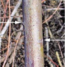 Figure 5-103 | Bud orientation on cuttings
The vertical orientation of buds on older willow (Salix spp.) stems can be visually difficult to discern (see arrows). Keeping track of the orientation of the bud from collection to installation is very important.
Photo credits: David Steinfeld
Live Stakes
Live stakes are individual cuttings that are inserted into the slope to physically stabilize the soil and, with time, grow into individual plants with dense, interconnecting roots that further increase soil stability. Live stakes are used to repair small earth slips and slumps (Sotir and Gray 1992) and as pole plantings for stabilizing streambanks (Bentrup and Hoag 1998). Joint planting refers to live stakes inserted into voids or openings between large rocks. The live stakes can take root and revegetate rock riprap sites or portions of fractured bedrock (Sotir and Gray 1992). Live stakes are also used in live fascine installations and to anchor erosion mats to the soil (Lewis 2000). In gullies, draws, or intermittent streams, live stakes are placed in rows as live silt fences (Polster 1997) to slow water velocities and catch sediments and other debris. In saturated soil conditions, where excavation for brush layering or fascines is not feasible, live stakes can be densely stuck by hand.
Collection—Live stakes are collected from the main stems of donor plants located in the wild (Section 5.3.2) or from stooling beds in nurseries (Section 5.3.5). The optimum period to collect cuttings is during the dormant period after the plants have lost their leaves. If cuttings are collected outside this period, testing the viability of the cutting material is essential (Section 5.3.2, see Determine Rooting Potential). It is important to collect cuttings with several dormant buds because this is where shoots will originate (Figure 5-103).
When preparing stakes, all side branches are removed, leaving just the stem. Only stems with diameters between 1 and 3 inches are used. Stems are cut into lengths of 1 to 3 feet, depending on how the materials will be used. It is important to select the appropriate cutting length. Stems that are too short will affect the success of the project, and cuttings that are too long will increase the costs of the project. During collection, basal ends of the cuttings are always oriented in the same direction to ensure that the buds will be aligned. This will help avoid confusion later when the stakes are being installed. Finding the orientation of the buds is often difficult (Figure 5-103) and having to reorient in the field takes time. As individual stakes are made, the top of the stake is cut flat, while the basal end is cut at an angle (Figure 5-104). This makes the stake easier to insert into the soil and orients the live stake so the buds are facing up and away from the soil surface. If buds are facing down, the live stake will not root.
During collection, live stakes are wrapped in small bundles with twine. It is important to keep the size of the bundle light enough to be easily carried. Once the bundle size has been determined, it is important that the numbers not vary in order to track cutting quantities. Stakes can be cut from healthy donor plants. Stems that have obvious insect or disease damage are not good for use. It is often easy to forget that live cuttings are plant materials, like seeds and seedlings, and should be handled and stored with care.
Storage—It is recommended that live, dormant stakes be collected and installed the same day (Sotir and Gray 1992; Lewis 2000). This is not always possible in a road construction project. When it is not, temporary cold storage is an option. Temperatures in these facilities are usually set below 40° F and, if humidifying equipment is available, it is helpful to keep it on high. For longer-term storage (over two weeks), good practices are to keep cuttings wrapped in plastic or moist burlap to prevent the vegetative material from drying out, and temperatures set just below freezing. Lower temperatures can result in damage and even death (Wearstler 2004). As a last resort, cuttings can be temporarily stored outside, provided daily temperatures are low (<50° F) and humidity is high, cuttings are completely wrapped in plastic, temperatures will not drop below 25° F, and the site is shaded from the sun.
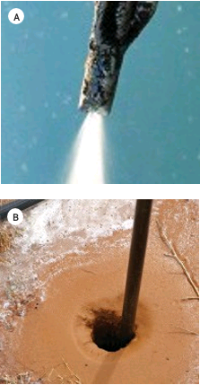
Figure 5-105 | Waterjet stinger
The Waterjet Stinger (A) injects high-pressure water into the soil, turning it to a slurry (B) into which a live stake can be inserted. Photo credits: Chris Hoag
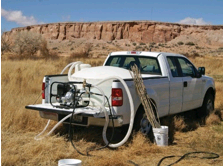
Figure 5-106 | Water tank with pump
A 250-gallon water tank with pump can be installed in the bed of a pickup truck to supply water for Waterjet Stinger sticking. Photo credits: Chris Hoag
Preparation—Studies of black willow (Salix nigra) have shown that soaking dormant cuttings prior to installation can increase survival (Schaff et al 2002; Martin et al 2005; Pezeshki et al 2005; Pezeshki and Shields 2006). Soaking for approximately 10 days appears to be the optimum period for black willow (Schaff et al 2002; Pezeshki and Shields 2006). Soaking non-dormant cuttings, however, appears to be detrimental to survival (Pezeshki et al 2005; Pezeshki and Shields 2006). Species native to the western United States might respond similarly to the black willow. The effects of soaking can be tested in other willow species using a method outlined in Section 5.3.2 (see Determine Rooting Potential). If live stakes are soaked in streams, it is important to be sure they are sufficiently protected from being swept downstream during high precipitation or snowmelt.
Installation—For most applications, live stakes are installed perpendicular to the soil surface. When installed, no more than one-quarter to one-fifth of the cutting is exposed (Sotir and Gray 1992; Darris and Williams 2001). Buds are always pointing up and away from the soil surface with at least two healthy buds above the soil surface. It is essential that soil be firmly packed around live stakes so there are no large air spaces surrounding the cutting. For successful sprouting the live stakes can be installed in locations and to a depth where soil moisture is consistently available. Live stakes can be installed using the techniques described in Section 5.4.4. These include a shovel, auger, or expandable stinger. In addition to these methods, several techniques are available specifically for live stake installation, which include a hammer, stinger, or Waterjet Stinger.
Hammer or Mallet—For best results a steel rod can be used to open a hole for the live stake and the stake inserted into the hole and the surrounding ground tamped to eliminate voids. Live stakes can be pounded into the ground using a hammer or mallet but this can abrade the bark, split the stake, and provide an opening to disease or fungus. If the stake is hammered the use of a dead blow hammer is recommended and the angled basal end of the stake is placed on soft soil surface and the top of the cutting is struck. A small 2 x 4 wood block can be placed on the top to absorb the impacts and reduce the risk of splintering the stake. If splintering does occur, the splintered ends can be cut (Lewis 2000). After cutting, it is best if several viable buds are still above the soil surface. Using a hammer or mallet works most effectively when soils are loose and low in rock fragments. It becomes more difficult as rock content or compaction increases. Smaller stem diameters are often not sturdy enough for this installation method.
Stinger—The stinger is a good method for installing live stakes on rocky or compacted soils. A pilot hole is created by mechanically pushing a metal rod into the soil. A live stake is inserted into the hole and tamped to the bottom using a hammer or mallet, as described above. Some operators will create the hole with the stinger and, after placement of the stake, use the face of the excavator or backhoe bucket to push the stake farther into the soil. The hole created by the stinger is often larger than the diameter of the stake, and the soil can be tamped in around the cutting to reduce air space and create good soil contact. A stinger can be made by welding a long piece of rebar to the bucket of an excavator or backhoe. The stinger is limited by slope gradient and terrain accessibility.
Waterjet Stinger—The Waterjet Stinger hydraulically creates a hole for installing live stakes. A pump draws water from a stream, lake, or water truck for delivery through a hose to the stinger nozzle. As the tip of the nozzle is pushed into the ground, high-pressure water is injected into the soil, creating a slurry (Figure 5-105). When the Waterjet Stinger is removed, a stake is quickly pushed into the resulting slurry at the desired depth. As water drains from the slurry, soil settles around the cutting, resulting in good soil contact.
The advantages of using the Waterjet Stinger are that it is simple to operate and transport; little training is necessary to use it; production rates are high; holes are deep, ensuring that cuttings are planted directly into a wet environment; soils are saturated around the cutting for a long period of time; and the soil slurry settles around the cutting ensuring good soil to stem contact, eliminating air pockets in the rooting zone (Hoag et al 2001). The disadvantage of the Waterjet Stinger is that it needs a nearby water source. If the project is not near a body of water, it can be brought in using a water truck or large water storage containers placed in the back of a truck (Figure 5-106). The Waterjet Stinger is also limited by the amount of rock present in the soil. This equipment does not work well in soils containing gravels, cobbles, and boulders that obstruct the downward movement of the probe (Hoag 2007). Sandy soils drain quickly, so installation of cuttings with the Waterjet Stinger is most effectively done quickly and with a little more effort. Steep slope gradients and rough terrain also limit equipment and the transportation of water. For more information on the Waterjet Stinger, refer to Hoag et al (2001).
Expandable Stinger—The expandable stinger can install live stakes into all soil types and soil conditions, from rocky to compacted. It can plant long cuttings (> 4 ft) and stems of most diameters (including very small diameters). The stake is placed into the stinger, which is inserted into the soil and released, leaving the cutting at the desired depth (Section 5.4.4, see Select Planting Tools and Methods). This installation method can leave large air spaces around cuttings. It is therefore recommended that soils be tamped around the cutting after placement.
Hand-Sticking—Hand-sticking is appropriate in areas where soils are mucky or saturated, including recent landslides and wetlands, and cuttings can easily be inserted into the soil. Because this installation method can be done quickly, areas can be planted at very high densities (Figure 5-107).
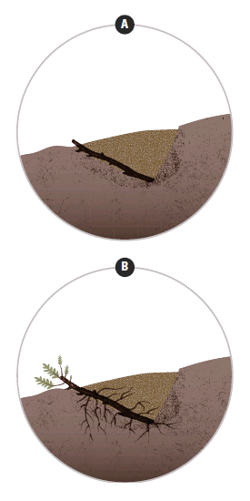
Figure 5-108 | Live brush layers
Live brush layers are cuttings that are placed on benches and covered with soil (A). The basal end of the cuttings extend back to the base of the bench, and the growing tip just shows out of the soil. When placed on the contour and at regular intervals, live brush layers form a network of roots and vegetation that tie the slope together in a series of strips, increasing slope stability and reducing erosion.
Live Brush Layers
Live brush layers are cuttings that are spread on excavated benches and covered by soil (Figure 5-108). This practice is used in several biotechnical engineering applications, including brush layers and modified brush layers. Constructing brush layers is a three-step process in which contour benches are excavated, live branches are spread across the bench surface, and branches are covered with soil from constructed benches directly upslope. The process begins at the bottom of the slope and is repeated until the entire slope is installed with brush layers. In a modified brush layer system, the brush layers are resting on, and supported by, logs or live fascines (Sloan 2001).
Brush layers and modified brush layers increase slope stability and reduce erosion by breaking slope length, reinforcing soil, trapping sediment, increasing infiltration, acting as horizontal drains, and reinforcing soil as cuttings develop roots (Sotir and Gray 1992). Live brush layers can also be used to vegetate crib walls, rock gabions, green walls, and rock walls. In this application, live branches are placed on benches that are created as these structures are built. For crib walls (Inset 5-22), live layers are placed on the bench created behind each layer of logs; in rock gabions, live layers are placed on each layer of gabion baskets.
Collection—Materials for live layering are obtained from branched cuttings collected in the wild or from stooling beds. Stems up to 2 inches in diameter can be used (Sotir and Gray 1992). The basal end of the cuttings is always oriented in the same direction during collection and bundling. It is good practice to keep cuttings for brush layers long enough that the growing tips are just exposed at the soil surface, while the basal portion of the cuttings reaches to the back of the bench (Sotir and Gray
1992). For rock gabions, rock walls, and crib walls, cuttings are effective whenthey are long enough to extend into soil or backfill behind the structures. During collection, cuttings are placed in bundles and secured with twine. Bundles light enough to carry are usually preferred. The optimum period to collect cuttings is during the dormant period when the plants have lost their leaves. If cuttings are collected outside of this period, then testing the viability of the cutting material is essential (Section 5.3.2, see Determine Rooting Potential). Fine branches dry out quickly if exposed to warm, dry temperatures. Protecting cuttings during transportation, storage, and handling can help avoid drying.
Storage—Refer to Section 5.4.3 (see Live Stakes).
Installation—Branched cuttings are laid out on benches so the basal end of the cutting reaches to the back of the bench and the growing tips extend just beyond the front. Soil is placed over the cuttings and tamped to ensure there are no large air spaces. Excessive compaction is unnecessary for plant establishment and is often detrimental for long-term plant growth (Section 3.8.2, see Soil Structure). The material used to cover live branches in or behind crib walls, rock gabions, and rock walls is often low in water-holding capacity, nutrients, and organic matter. Soil amendments, such as compost, can be incorporated into backfill material to improve water-holding capacity and to serve as a long-term source of nutrients and organic matter. These amendments can increase establishment and improve plant growth (Section 5.2.5). Waiting until after the construction of crib walls, rock gabions, and rock walls to amend the soil is not practical or feasible.
Inset 5-22 | When should seedlings or rooted cuttings be substituted for live cuttings?
Live cuttings are widely used in biotechnical engineering projects. Sometimes, however, it is more practical to substitute rooted cuttings or seedlings in place of live cuttings. This is especially the case when the road project calls for cuttings to be planted in the summer or fall; when dormant, live cuttings are not available; or when live cutting material is not available in large enough quantities.
For example, a road near a designated Wild and Scenic River is being widened. Biotechnical engineering techniques using live willow cuttings are being planned for retaining walls to increase slope stability in areas adjacent to the river. The design looks good on paper (A). However, when discussing the details with a designer, questions arise: where will the cuttings be collected and what time of year will the willows be installed? Upon inventorying the willow stands on the district, they learn there is not a supply of willows large enough to meet the needs of the project. To obtain this volume and size of cuttings, the establishment of stooling beds at a nursery would be required (Section 5.3.5), which would take at least two years prior to project implementation.
More disturbing, they learn that the contract can only be implemented in the summer due to water quality and wildlife restrictions. While some cuttings installed in the summer would sprout, most would not, as was determined through rooting potential testing (Section 5.3.2, see Determine Rooting Potential). Referring back to the project objective, the design engineer and the designer realize that going ahead with the project, as designed, would compromise revegetation of the retaining wall. The decision was made to adopt an alternative design to install rooted cuttings grown in long tubes (at a nursery) instead of unrooted cuttings. The rooted cuttings would be planted at very high densities where the brush layers were to be installed (B). Because only a small amount of cuttings would be necessary to start rooted cuttings in containers at the nursery, there was no need to develop stooling beds, eliminating the extra time and costs to produce these plant materials.
The stems of the long-tube rooted cuttings can be set back several feet into the soil (circled in B) as long as a portion of the foliage is above ground. This will add length to the rooting area and the stems will initiate roots (C).
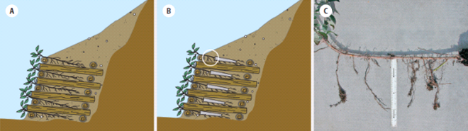
Live Fascines
Live fascines are cuttings bound together to form a long continuous bundle (Figure 5-109). When installed on the contour, live fascines slow runoff, increase infiltration rate, capture sediments, reduce slope length, and revegetate the site (Sotir and Gray 1992). Live fascines have a good potential for quick establishment because of the high density of buds near the surface of the soil. Live fascines can quickly send out shoots and roots early in the growing season and become established before summer (Figure 5-109).
Fascines are used in the construction of live pole drains to drain saturated slopes, small slumps, or gullies (Polster 1997). Live pole drains are designed to intercept surface water from unstable slopes or seepage areas, and transmit it through a system of interconnecting bundles to more stable areas (Section 3.8.6, see Water Input). The constant supply of intercepted water encourages vigorous growth of the cutting material into a continuous stand of vegetation. Fascines are also used as the base or support in the construction of modified brush layers. Live fascines have great potential for establishment because of the high density of buds just under the surface of the soil. These buds can emerge quickly in late winter and early spring. Because they are installed at the soil surface, live fascines are more prone to drying out than live brush layers or live stakes. For this reason, live fascines are more successful on moist sites or in conjunction with live brush layering or live staking.
Collection—Branches and stems up to 2 inches in diameter are collected from the wild or from stooling beds and gathered to form a long continuous bundle. Fascines vary in length from 5 to 30 feet, and from 6 to 8 inches in diameter. For large projects, construction of a series of sawhorse-type structures makes this operation easier and more efficient (Sotir and Gray 1992). At frequent intervals, bundles are secured with twine to hold the fascines together. Cuttings can be collected during the dormant season when the plants have lost their leaves. Fine branches dry out quickly if exposed to warm, dry temperatures and are to be protected during transportation, storage, and handling.
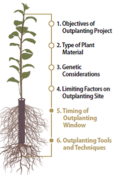
Figure 5-110 | Target plant concept
The final two steps of the Target Seedling Concept, the Outplanting Window and Planting Tools, and Techniques, are considered before initiating planting projects (adapted from Landis 2009).
Storage—Refer to the discussion in Section 5.4.3 (see Live Stakes).
Installation—Prior to installation, trenches can be created at the proper depth so the top of the fascine is flush to the surface of the slope when installed. The shape of the most effective trenches allow soil contact with all portions of the bundle. Soil is tamped down around the sides of the bundles to ensure soil contact, and the upper fifth of the bundle is covered by a thin layer (<1 inch) of soil. A very small portion of the fascine is usually left exposed, but not enough to dry the stems. If the fascine is buried too deeply, vegetative growth will be restricted.
5.4.4 INSTALLING PLANTS
Introduction
Although a wealth of information exists about planting for reforestation, very little information has been published about planting nursery stock on roadsides. Several references can be found discussing harsh site reclamation. Ashby and Vogel (1993) is an excellent source for planting on restored minelands.
Before beginning a planting project, the revegetation plan and plant production contract can be reviewed carefully, as can the Target Seedling Concept (Figure 5-110) which was considered during the planning process (Section 3.13.1). The first four steps were covered when plants were ordered during the planning process. The timing of the outplanting window and planting tools can be considered at this time.
Timing of the Outplanting Window—The outplanting window is the period in which environmental conditions on the outplanting site are most favorable for survival and growth of nursery stock (Figure 5-111). The outplanting window is usually defined by limiting factors, and soil moisture and temperature are frequent constraints. In most of the continental United States, nursery stock is outplanted during the rains of winter or early spring when soil moisture is high and evapotranspirational losses are low. Fall outplanting is another option on some projects, especially when dormant and hardy plants can be installed just before the normal rainy season begins. Planting during the summer is usually discouraged because the nursery stock is not dormant and will experience severe transplant shock. If nursery stock is carefully handled and plants can be irrigated, then summer plantings are possible.
Planting Tools and Techniques—Nursery stocktype and the conditions on each outplanting site are usually considered before planting begins. All too often, planters develop a preference for a particular planting implement because it has worked well in the past. However, no one tool will work for all types of nursery plants and under all site conditions. Size of nursery stock, in particular the depth and width of the root plug, is the critical consideration. Tall pots, for example, have an unusually deep root plug, which makes them difficult to plant properly with standard tools. For some types of plants and, especially, for large planting projects, it may be necessary to buy or rent specialized equipment, that can be secured in advance. The planting tools recommended for roadside revegetation projects are discussed in Section 5.4.4 (see Select Planting Tools and Methods).
Define Planting Areas
When construction is completed, the project site is assessed for planting. A detailed map showing the exact planting locations and conditions is developed by reviewing each location on the ground. Each area can be identified on a map and described in a spreadsheet by the following:
- Planting area acreage
- Planting patterns
- Plant spacing (density)
- Survival potential
- Species and stocktype mix
With this information, a planting strategy can be developed for each planting area using calculations similar to those shown in Figure 5-112.
Size of Planting Areas—The first step is to measure the area of each planting unit. Although they could be calculated from Project plans or acquired from the electronic files, the true planting areas can be measured on-site. A practical method is described in Figure 5-113.
Planting Patterns—The pattern at which nursery stock is planted is critical for creating a more natural and visually pleasing roadside experience. Most planters have learned to install plants at uniform spacing and in rows (Figure 5-114A). Although uniform patterns ensure that all plants have equal growing space, it is not natural. Planting seedlings in groups (Figure 5-114B) or clumps (Figure 5-114C) is more visually appealing and more ecologically functional. Maintenance or roadsides can be considered in the location and spacing of plants.
The operational right of way will include an obstruction free run-off area or “clear zone” next to the roadway. This clear zone would allow a driver to recover from an off-pavement event with potentially no or minor damage to the vehicle. The clear zone will also be kept in such a manner that roadside vegetation does not provide cover to wildlife. The well designed planting pattern of vegetation beyond the clear zone will determine what maintenance practices are performed on this section of roadway and accommodate the required equipment’s width and turning ability in the spacing and location of vegetation. Vegetation that benefits pollinators would include trees, shrubs and flowering forbs as well as native grasses. Plantings with all of these arranged in a foreground, middle-ground and back-ground design can be discussed with maintenance staff so that grasses and forbs that skirt the shrubs will be allowed to remain.
The revegetation specialist can meet with maintenance staff during the planning stage. Maintenance operations, especially mowing and herbicide use are significant reasons that limit roadsides as pollinator habitat. Mowing interrupts the life cycle of most wildflowers, preventing their blooming and subsequent reseeding, and over time effectively eliminating the plants from the roadside landscape. If the revegetation specialist is not able to agree on with maintenance personnel on practices that allow flowering plants to persist, then the expensive wildflower seeds can be removed from the proposed seed mix.
More specific considerations about planting patterns are based on project objectives and site characteristics. Topography and soil characteristics are two important site characteristics that can inform planting patterns. If one of the project objectives is to support wildlife, then topography can be used to design planting patterns that provide shelter (e.g., clumped trees at the bottom of a ravine) or migrations routes (e.g., trees planted as covering screens leading towards adjoining natural areas). Very sandy or serpentine soils may be avoided at a site and the spatial pattern of these soils will inform planting patters. A typical example would be to use plants to screen potentially unattractive areas, such as large cuts and fill or obliterated roads. Screen plantings can also be used to screen views of the roadway from adjacent properties. Plantings can frame and highlight attractive views. Locations of plants can be organized at intersections or points of interest to differentiate the location from the surrounding landscape. The potential to influence the road user’s experience is very high. Long monotonous landscapes of homogenous plantings can lull a driver to sleep and can be an unsafe distraction. A roadside that provides variety in form, color and use of materials can enliven the driver’s experience. Landscape architects and designers using the many principles of design can exploit opportunities that may not be evident to a botanist or engineer. A thorough site analysis incorporating views from the road alignment (both directions) and views toward the road from adjacent properties is important in determining of where trees or shrubs should be planted to create views or screen views as the situation demands.
Plant Spacing—The planting spacing or density will determine how quickly an area will become screened by vegetation. The higher the density, the more plants are required. Selecting the appropriate density can be based on the existing vegetation density recorded at reference sites, as well as both short- and long-term project objectives. It can also be based on the expected survival rates of the planted stock, because not all planted stock will survive.
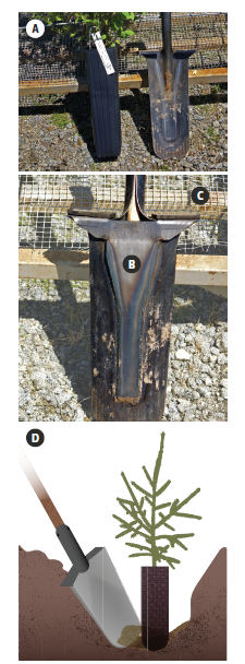
Figure 5-115 | Tile spade shovels
The objectives of the outplanting project and desired appearance affect planting patterns. If the objective is rapid growth and quick site coverage, the plants can be regularly spaced (A). However, plants spaced in a more random pattern mimic natural conditions (B), and a random-clumped pattern where different species are planted in groups is often the most natural appearing (C) (adapted from Landis and Dumroese 2006).
Survival Potential—Each planting area can be assessed for its unique site characteristics, such as rock content, soil depth, accessibility, steep slopes, and poor accessibility. These will determine the stocktype and species selection, method of planting, and the difficulty of transporting large plants to the site. The identified site limitations will determine the expected survival rates; having target survival rates be at least 70 percent can minimize the costs of site preparation and anticipated replanting.
Species Mix and Stocktype—Each planting area will have a different mix of species and stocktypes based on the site characteristics and project objectives defined during the planning stages. This is a refinement of those plans based on a site-specific evaluation of the area. Trees and other large woody plants are considered “keystone species” because of their sheer size and longevity. These structurally and functionally dominant plants play a pivotal role in restoration plantings because they generate physical structure and create ecological niches for many other species. This fosters the in-seeding of other plants, resulting in a more natural and visually appealing landscape. Selecting a variety of species of flowering forbs can be effective when providing habitat to pollinators. Besides being regionally endemic, species can be selected that have flowering periods overlap so that, from early spring through late fall, at least one or more species is flowering to provide nectar and pollen to insects.
Select Planting Tools and Methods
One planting method will rarely work for all planting areas and all species in a revegetation project. Roadside sites offer some serious challenges to planting nursery stock, most notably highly compacted soils and often a high percentage of rock. Road projects create the opportunity for unique situations, such as planting islands.
The most common type of planting method is manual planting using a shovel. Recent developments in mechanized planting equipment have increased the tools available. The most common types of planting tools for roadside revegetation sites are described below.
Shovel—The versatile “tile spade” shovel (Figure 5-115A) is the first choice for compacted soils and stocktypes used in roadside revegetation. Forestry supply companies sell a specialized planting shovel with a 14-by-5-inch blade, a welded reinforcement plate on the back of the blade (Figure 5-115B), and rubber padded footplates (Figure 5-115C). Shovels work well when planting both bareroot and container stock, as well as bulbs and other plant materials that do not require holes deeper than 1 foot. Working the shovel blade back and forth breaks up compacted soil and can create a planting hole for large container stock (Figure 5-115D). Practical sites are accessible for hand planters, and the soils are not too rocky or shallow. Very steep slopes (1:1 or greater) make shovel planting very slow and difficult.
Power Auger—Power augers can be an excellent and efficient way to excavate holes for planting (Figure 5-116A). Many types of augers are available: one-person operated, two-person operated, and a chain saw modification. There are also larger augers that can be mounted on larger mobile equipment such skid steers. A wide variety of auger sizes means that this one implement can work for many stocktypes. Augers are particularly good for large container stock. For example, a 4-inch auger bit creates planting holes that will just fit the root plug of a “Tall Pot” container plant, ensuring good root-to-soil contact (Figure 5-116B). In a comprehensive review of planting tools, Kloetzel (2004) concluded that, when container size is larger than 336 ml (20 in3), power augers will boost production under most soil conditions. It is most efficient to have one person operating the auger, with several people planting behind the operator. A down side of excavating with an auger is that when used in compacted soils the narrow planting pit can act as container that inhibits root growth beyond the limited area of backfill. Widening the hole and scarifying the sides can diminish this effect. Auger planting is effective on restoration sites because one person determines the location and pattern of the planting holes. Production rates are reduced with rocky or compacted soils, but a drill auger with a special bit has been developed for planting large container stock in rocky soils (St. Amour 1998).
Expandable Stinger—Specialized planting equipment is needed for the rocky and steep slopes that are often found along roadways. The original stinger was a pointed metal bar that was hydraulically forced into the soil to plant willow and cottonwood cuttings. The expandable stinger is a recently developed planting device attached to the arm of an excavator (Figure 5-117) that creates a hole and plants the seedling all in one operation. The planting head is composed of two parallel steel shafts that are hinged in the middle to open and close in a scissor-like manner. Each shaft is constructed to create a long hollow chamber between them when closed. The opening and closing of the shafts are hydraulically driven. When the shafts are closed, the stinger comes to a point and is pushed into the soil by the force of the excavator arm. A long hardwood cutting or container plant is placed into the chamber. The expandable stinger is maneuvered to the planting spot, where the beak is inserted into the soil. When the beak opens, the seedling drops to the bottom of the hole leaving the seedling in place (Figure 5-117B and D).
At least two expandable stinger models are currently in use. The single-shot model inserts plants one at a time and averages between 50 to 80 seedlings per hour. The 50-shot model contains a rotary magazine that can hold 50 plants of up to three different species and can double the planting rate of the single-shot model (Kloetzel 2004).
The advantage of this equipment is that it can reach very steep cut-and-fill slopes—sites that are inaccessible by other planting methods. Smaller excavators can reach 25 feet, while larger machines extend planting up to a 50-foot radius, which is adequate for most cut-and-fill slopes.
This equipment can also plant in very rocky soil conditions, including riprap and gabions, and can insert plants up to 6 feet. With the typically compacted soils on roadside sites, the action of the beak of the expandable stinger breaks up the compaction around the planting hole. While soil typically falls back around the root plug after the expandable stinger has planted the seedling, it is still important to determine whether additional soil should be filled and tamped around the plant. Poor soil contact with the root system can reduce survival and growth during establishment.
The major drawback to the expandable stinger is the expense. Because of the high hourly rate of an operator and equipment, it is important that the expandable stinger be working at full capacity at all times. Good planning is essential. This means that all the planting sites are laid out before the equipment arrives; there is a clear understanding of species mix and planting for each planting area; seedlings are on the site and ready for loading into the equipment; and there is enough personnel to keep the equipment going. In a well-planned operation, the expandable stinger can plant up to 200 seedlings in an hour. In addition to the hourly operating costs, the mobilization costs can be very high, especially if the excavator and expandable stinger are transported a long distance. These costs can be spread across all seedlings being planted for a true cost. The more seedlings that are planted by the expandable stinger at one construction site, the less it will cost per planted seedling. Larger planting projects (>1,500 seedlings) spread these costs over more seedlings and make expandable stinger projects economical.
Pot Planter—The pot planter is a modification of the Waterjet Stinger (Section 5.4.3) that creates planting holes large enough for container plants. As with the Waterjet Stinger, it draws water from a water source (e.g., a lake, stream, or water truck) and hydraulically creates a planting hole as the tip of the high pressure nozzle is pushed into the soil (Figure 5-118A). The pot planter has 3-inch vanes attached to the sides of the nozzle, which create holes large enough for containers up to 1 gallon (Figure 5-118B). The hole that is created by the pot planter is actually a soil slurry that is displaced when the root plug is pushed into it at the desired planting depth. Once the water drains from the slurry into the surrounding soil, the soil settles in around the root plug, ensuring good soil-to-root contact.
The advantages of using a pot planter are that the container plugs are thoroughly moistened at outplanting; there are fewer air pockets in the soil and better root-to-soil contact; and soil around the planting hole is moistened, allowing roots more time to move out of the plug and into the native soil. These advantages create the opportunity for earlier fall planting, even as early as late August to early September in some areas. The earlier the fall planting, the greater the chance for rooting to occur before winter sets in. This rooting will be in addition to the root growth that occurs the following spring and can make the difference in whether a seedling survives the first growing season. Large containers can be planted quickly at a rate of approximately one plant per minute (Hoag 2006). The pot planter is limited by the same factors as the Waterjet Stinger, which include steep slope gradients, inaccessibility, high soil rock content, and poor water source availability.
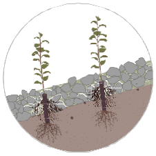
Figure 5-119 | Plants integrated with engineered structures
Engineered structures of gabions and riprap often require tall nursery stock and special installation techniques. When properly installed, however, plants survive and grow well, greatly increasing the visual appearance of the structure.
Planting into Engineered Structures—Occasionally, seedlings will be planted as engineered structures are being built. These structures include vegetated gabion walls, other “green” walls (Inset 5-22). Well-planned plantings are integrated into the construction schedule. Because road construction often occurs in summer when plants are in full growth, special handling methods and irrigation can be implemented during installation to ensure optimum seedling establishment (Figure 5-119). The installation of plants into riprap, for example, usually requires good planning and integration into construction activities. Drawings and a set of planting instructions are essential. Seedlings are partially planted in the existing soil and partially in riprap. Riprap and soil are hand placed around the seedling plug to ensure good root-to-soil contact and that the seedlings are handled with care. The remainder of the riprap is placed and the seedlings are irrigated. Each vegetated engineered structure involves different sets of instructions and drawings that are specific to the objectives and environmental conditions of the site.
Assess Plant Inventories
Depending on the size and scope of the project, many combinations of species, seedlots, and stocktypes may be grown at one or more nurseries. Seedling inventories from all nurseries where the stock is being grown can be consolidated into one list. Each nursery will supply a list of the quantity of seedlings in each seedlot that meet the contract specifications. This list may not exactly meet the original order. It is rare that the original seedling order ever gets filled exactly as requested. Some seedlots grow well, while others grow poorly, and this is reflected in the seedling inventory. There may be more seedlings in one seedlot and less in another.
Plant inventories do not always provide the full story about seedlots. Prior to putting together a planting plan, a visit to the nurseries will provide a full picture of the status of each seedlot. Stressed seedlings, poor roots, root-bound seedlings, disease, and other problems can only be realized by visiting the nursery months before plants are received. The visit to the nursery is not always a negative fact-finding mission. It can be approached as a problem-solving trip. For example, an inventory might indicate that certain seedlots do not meet size specifications. A closer review at the nursery may show that many of the seedlings that do not meet size specifications would be suitable in certain planting areas. If inventories are low, discussions with the nursery manager might bring up the possibilities of substituting surplus seedlots from other clients for the downfall in the inventory.
Match Inventories to Planting Area
At this point, the information developed during the location of planting units, including seedling density, species, and stocktype, can be reevaluated in light of the newest seedling inventory. In other words, the seedlings from the inventory can now be divided between planting areas in a manner that still meets the project objectives.
Using the spreadsheet in Figure 5-120 is a simple way to reconcile the differences between the plants needed at each planting area and the plant inventory. In this example, three planting areas are defined (A1, A2, and B). For each planting area, the number of plants of each species/ stocktype is listed. The planned needs are summarized in Line A. When the seedling inventory (Line B) is received, it is discovered that there will not be enough ponderosa pine (PIPO) or quaking aspen (POTR5) to meet the planned needs. The deficits are circled in Line C. In this example, seedlings can either be obtained from other sources or plant needs can be adjusted downward. In this example, the PIPO and POTR5 were adjusted downward because no substitute trees could be found to make up the difference. Saskatoon serviceberry (AMAL2) was adjusted upward as a partial substitution for the shortfall of tree seedlings. Plant spacing was recalculated from Figure 5-113 with a resulting increase of approximately 1 foot for both PIPO and POTR5. The extra antelope bitterbrush (PUTR2) and bitter cherry (PREM) were not planted (Line F) but rather surplused to a local landowner. Many more rows and columns can be added to this spreadsheet to accommodate more species and planting areas.
Transport Plants
The delivery of seedlings to the planting site is not generally the responsibility of the nursery. It can be an item in the seedling production contract, a separate transportation contract, or they can be transported by the designer. Whichever method is used, it is important that seedlings not be damaged during transportation by poor handling, hot temperatures, or drying conditions. Plants that have been packed in bags or boxes are protected from drying conditions and can be transported in most vehicles. If containers are transported in open pickups, they can be covered with a space blanket or special tarps to moderate temperatures and minimize the potential for desiccation (Figure 5-121). Specially constructed Mylar® tarps can be purchased from forestry or restoration supply companies.
Plants that have been kept in freezer storage can be thawed prior to transportation and planting. While small container stock has been shown to have satisfactory survival when planted frozen, there is no indication that large stock will perform the same. Once frozen seedlings have been thawed or cooler-stored seedlings have been allowed to warm, they can be planted immediately. Seedling viability will decrease if they are placed back into cold storage for more than a few days.
Plants that have not been packed in storage containers can be transported in enclosed units. Transporting plants in open vehicles, such as pickups, exposes foliage to strong, drying winds that can unduly stress the plants. Large container plants typically stand 2 to 4 feet tall (including the container) and require transportation with enough space to accommodate their size.
Develop Planting Contract
The following discussion outlines some of the basic components that could be addressed in a planting contract.
Location PREM—A map of the planting areas can be included in the contract.
Planting Quantities—The quantity of species, by stocktype, can be presented for each planting area.
Planting Method—There might be several planting methods that could be indicated for each stocktype and planting area.
Plant Spacing Requirements—For each planting area, describe or define the plant spacing at which each species will be planted. Calculations to determine the proper spacing between plants was presented in Figure 5-112. Approximate distance between plants can be determined graphically by knowing the target plants per acre, and, in reverse, the plants per acre can be determined by knowing the target spacing between plants (Figure 5-122). For example, if the plan calls for a density of 600 seedlings to be planted per acre, the spacing between plants would be around 8.5 feet (Line A in Figure 5-122). If the plan calls for 600 seedlings to be planted in planting pockets of three plants per pocket, there would be 200 planting pockets spaced approximately 15 feet apart (Line B in Figure 5-122). In another example, to determine the number of seedlings to order for a given area with a target spacing of 6 feet, the number of plants required would be just under 1,100 seedlings (Line C in Figure 5-122).
These spacing requirements are an average. Depending on the plantability of a site, the specified average spacing may vary up to 25 percent in any direction to find a suitable planting spot. Where an unplantable spot is encountered, the planter will plant in the closest plantable spot. Whenever possible, plants can be installed next to stumps, logs, or other obstacles that provide partial protection from sun, wind, and animals. If planting islands are designed into the planting areas, it is good practice for the contract inspector to mark each island within the planting area and have the species mix stated in the contract.
Handling Care—Handling plants with care can prevent damage to roots and foliage. Seedlings are best when not thrown, dropped, hit, or otherwise mechanically impacted. Extracting the root plug from the container can be done gently, avoiding excessive force when pulling the seedling from the container. Seedlings are typically not to be removed from containers until the hole is excavated. The container is then removed, and the seedling is quickly planted. Excessive exposure of the root system to air will decrease seedling survival and growth (Greaves and Hermann 1978).
Root Pruning—The bottoms of some containers are poorly designed, causing roots to circle or build up at the bottom of the pot (Figure 5-123A). However, quality nurseries will typically not use these inferior containers. But if these containers are utilized, damaged roots can be cut prior to planting to prevent potential root strangling, especially for tap-rooted woody species (Figure 5-123B). Root pruning is best accomplished at the nursery, but this can be stated in the growing contract to cover the added expense. Pruning in the field is not recommended because of the increased root exposure. However, it may be necessary when nursery stock arrives with constricted roots.
Container Moisture—Root plugs that are dry can be thoroughly moistened prior to planting. Irrigating seedlings at the nursery several days before shipping and again on the day of shipping ensures that root plugs are completely wet. It is helpful to convey these instructions s to the nursery manager prior to picking up the seedlings. Provisions can be included in the contract that address the need for wetting root systems should they be dry at the time of planting. Wetting rootplugs can be accomplished by dipping seedling containers into a large water container, such as a cattle trough or trash can, prior to planting. Planting seedlings using the pot planter ensures that the root plugs are wet at planting.
Temporary Storage—If container plants cannot be planted in one day, they can be stored in the field in a well-sheltered area protected from the sun and animals. Reflective tarps are recommended to keep plants cool and moist during on-site storage (Figure 5-121). If container plants are left out for several days, it is important that the root plug not be allowed to dry out. If they do lose moisture, it is likely necessary to irrigate the containers prior to planting. Plants that have been extracted and placed in storage boxes or bags are likely most viable when returned to a local cooler for storage.
Clearing and scalping dimensions can be stated in the contract. Planting holes are usually best when located near the center of the prepared planting spot and be dug vertically rather than perpendicular to the ground surface. The planting hole is typically 3 to 4 inches deeper than the total length of the root system or root plug, and wide enough to fully accommodate the width of the root system. It is good practice to place seedlings in the hole so that the cotyledon scar (the bump or constricted area on the seedling stem that is the transition from the root system to the stem) is 1 inch below the ground line. Species that can be rooted from cuttings can be planted deeper because portions of the stem will root when buried. It is recommended that the root plugs not be forced into the planting hole, distorted, or broken during planting. After placing the plant in the hole, excavated soil is placed firmly around the root system so that there is no loose soil or air pockets around the root plug and the root system is not damaged. A small circular water-holding basin can be created around each seedling after planting to capture water or store irrigation water.
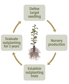
Figure 5-124 | Monitoring outplanting results informs future decisions
Monitoring the survival and growth of nursery stock for several years after planting provides valuable information for future projects.
Planting—Prior to preparing the planting hole, the planters should clear the surface of the planting spot of all limbs, logs, snow, duff, litter, rocks, and other loose debris. If sod, crowns of living plants, and roots are present, they can be scalped down to moist mineral soils.
Administer Contract
The planting contract inspector schedules the shipment of seedlings from the nursery, be certain that root plugs are moist and ready for planting, have the right quantities of plants at each planting area, and inspect the contract. In addition, if there are special planting patterns designed for the planting area, these may need to be marked on the site prior to planting.
The planting inspector also determines if the conditions are favorable for planting. Seedlings are usually not to be planted into dry soil unless the planting spot is irrigated immediately after planting or the pot planter method is being used. Under certain circumstances, high moisture soils follow geomorphic features, such as creek or river terraces where high ground water brings moisture to the soil surface. These sites can be identified on the ground at the time of planting.
Monitor Planting Success
Valuable information can be obtained by monitoring nursery stock for several years after planting. The first few months are critical because nursery plants that die immediately after outplanting indicate a problem with nursery stock quality. Plants that survive initially, but gradually lose vigor, indicate poor planting or drought conditions. Therefore, plots can be monitored during and at the end of the first year for initial survival. Subsequent checks after three years will provide a good indication of plant growth potential (Figure 5-124). This performance information is then used to provide valuable feedback to the nursery manager, who can fine-tune the target specifications for the next crop.
Back to top
5.5 POST-INSTALLATION CARE OF PLANT MATERIALS
The first year after plant materials are installed on a project site is typically the most critical period in a revegetation project because this is when plants become established. Applying the appropriate mitigation measures to improve the site and soil conditions prior to installation of plant materials greatly increases the chances of plant establishment. Sometimes even these measures are not enough to overcome limiting site factors. The implementation guides in this section cover several post-installation measures that can be conducted to increase the potential of plant establishment.
Establishing plants from nursery stock is often limited by animal browsing. Section 5.5.2 covers the methods available for protecting plants from different forms of animal damage. On hot, dry sites, plants need to be shaded from mid- to late afternoon solar radiation. The application of shade cards (Section 5.5.3) is one method for protecting young plants from heat stresses. Moderating the climate around plants from extreme temperatures and high evapotranspiration rates is sometimes accomplished through the use of tree shelters. Section 5.5.4 outlines when these structures are used, product types, and how they are applied. Some projects require supplemental irrigation for establishing seedlings on extremely dry sites. Section 5.5.5 discusses two types of irrigation used in revegetation projects: deep pot irrigation and drip irrigation.
5.5.1 INTRODUCTION
The first several years after the installation of seedlings are critical for the survival of healthy nursery plants. In the western United States, nursery plants die because of animal damage, high surface temperatures, high evapotranspiration rates, lack of soil moisture, and vegetative competition. This section describes certain steps to reduce these impacts. Where animal browsing is high, fencing, netting, and animal repellants are important to consider (Section 5.5.2). For high surface soil temperatures shade cards can be used to protect seedlings (Section 5.5.3). Reducing evapotranspiration rates is achieved using tree shelters (Section 5.5.4) and shade cards. Some high visibility projects require fast growth rates and low risk in plant establishment, in which case irrigation can be considered (Section 5.5.5). Additional measures that benefit seedling survival are covered in other sections. These include applying mulch around seedlings to conserve soil moisture and reduce vegetative competition (Section 5.2.1, Section 5.2.3 and Section 5.2.7).
5.5.2 ANIMAL PROTECTION
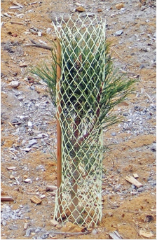
Figure 5-125 | Rigid netting
Rigid netting can protect seedlings from deer, elk, and gopher damage. The net- ting in this picture was installed 3 inches below the ground line to protect the seedling from gophers while the foliage and terminal leader are protected from deer and elk browsing. Photo credit: David Steinfeld
Planted seedlings can be damaged by a variety of animals, including cattle, deer, elk, gophers, and voles. While some damage by animals can be expected, excessive damage can be prevented. A variety of methods can be used to protect seedlings, including rigid and non-rigid netting, fencing, and animal repellents.
Netting
A common practice for protecting seedlings from browsing animals is to install a plastic netting over each seedling. The netting acts as a barrier to foraging of foliage, stems, and even root systems without impeding plant growth. It has been used to protect seedlings from deer, elk, gophers, and other ground-burrowing animals.
The two general types of netting are rigid and non-rigid. Non-rigid netting is a soft, fine-mesh plastic material. When installed on a seedling, it fits snuggly around the foliage like a sock. The rigid netting (Figure 5-125) has larger mesh openings and holds its form when installed. Rigid netting, while typically more expensive, is usually preferred over non-rigid because it is easier to install and seedling growth inside the netting is less restricted.
Netting could be installed as soon after planting as possible to ensure immediate protection. If installation occurs after bud break, it is important to take care to avoid breaking or damaging the terminal leaders or buds. Rigid netting is held in place with one or two bamboo stakes woven through the netting at three places and driven into the soil at a minimum depth of 8 inches. For deer and elk protection, netting is placed so the height of the netting is several inches or more above the terminal bud. Non-rigid netting is simply placed over the foliage like a sock and not secured with stakes. Rigid netting can offer some protection from gopher damage if the netting is installed more than several inches below the surface of the soil (Figure 5-125).
The effectiveness of netting decreases as the terminal leader grows out of the rigid netting and become susceptible to browsing. At this point, the netting can be repositioned upward to protect the terminal leader, which requires annual maintenance. At some point, netting can be removed entirely to avoid restricting seedling growth and ultimately killing the seedling. Some netting has been manufactured with photodegradable material that will break down within several years, eliminating the need for removal. Nevertheless, it is useful to visit sites that have had any type of plastic netting installed on seedlings several years after planting to determine whether the plastic netting is degrading or needs to be removed.
Fencing
Fencing is often used to protect planted or seeded areas from wild ungulate and livestock grazing or trampling. Each group of animals has different fencing specifications. Fence height for wild ungulates typically requires 8 to 12 feet (Helgerson et al 1992), while fence height for livestock is 4 to 5 feet. It is good practice to install fences prior to seeding or planting to ensure optimal plant establishment.
Fencing entire planting or seeding areas is expensive to install and maintain. Maintenance is a high priority because one break or opening in the fence will likely place the entire project at risk. It is recommended that fences be monitored and maintained at least weekly and up to three times per week during peak browse season (Greaves et al 1978). Fences can be designed with one or more gates to allow domestic or wild ungulates or other species to escape if they become trapped.
An alternative to fencing entire planting areas is to fence strategically located areas, such as planting islands. Fenced areas, called exclosures, range in diameter from 6 to 15 feet and are typically constructed with a 14-gauge, galvanized welded wire mesh (2- by 4-inch openings). Fence heights can be reduced around small diameter exclosures because wild ungulates are less likely to jump into small areas (Gobar 2006). In this strategy, the smaller size and greater number of exclosures reduce the risk of a failed project. After seedlings have grown high enough to withstand grazing and browsing pressures, small enclosures can be removed.
Animal Repellent
Browsing by deer and elk can be temporarily controlled by applying animal repellents to the foliage of seedlings. A variety of repellents are on the market with varying degrees of effectiveness. Trent et al (2001) tested 20 products for effectiveness in reducing deer browse on western red cedar (Thuja plicata) seedlings and found that products emitting sulfurous odors were the most effective. These products contain active ingredients such as “putrescent whole egg solids” or “meat meal.” Less effective products were those causing pain or irritation, containing active ingredients such as capsaicin, garlic, and dlimonene. Of the products tested, the least effective repellents protected seedlings for a few weeks, while the most effective protected seedlings for up to three months. Because seedlings are generally more palatable after winter dormancy, deer repellents are best applied just before bud break (Helgerson et al 1992) and at several month intervals during the active growing period as needed. Animal repellents in a hydrophilic powder formulation are reported to adhere better and last longer in climates with high rainfall than liquid forms (Helgerson et al 1992). Additionally dyes can be incorporated to indicate the presence of these repellents which be useful to monitor application patterns.
5.5.3 SHADE CARDS
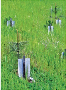
Figure 5-126 | Shade cards
Shade cards are placed on the south side of the seedling so the shadow cast by the shelter protects the lower portion of the seedling. This photo was taken two years after shade card placement. Photo credit: David Steinfeld
Because high soil surface temperatures can limit seedling survival and growth, it is important that the stem of the seedling (where heat buildup occurs and causes the most damage) is shaded from the sun (Childs and Flint 1987). Seedlings can be planted next to obstructions, such as logs, to utilize the shade these structures provide. Unless the placement of obstacles is planned into the project, construction sites will usually be free of material large enough to cast shadows. An alternative, but less effective, method of creating shade is using shade cards. Shade cards small, easy-to-install structures that shade the lower portions of the seedling from surface soil temperatures (Figure 5-126). Tesch and Helms (1992) reviewed numerous studies that evaluated the effects of shade cards on planted seedlings and found that, while the use of shade cards can significantly improve seedling survival, consider using them only on sites where several revegetation conditions are suboptimal, including south-facing aspects, sites with high winds, or when planting small, poor quality stock.
To be effective, shade cards are to be installed in the spring after planting and before hot weather sets in. It is important to know where the shadow of the installed shade card will be cast in order to know where to place the card. The shadow should cast shade on the stem and lower portions of the seedling to protect these areas from high surface temperatures during the hottest portion of the day (Childs and Flint 1987). The length of the shadow is dependent on the longitude, date, time of day, slope angle, and height of the shade card. Improper installation of shade cards is a common mistake, which typically occurs when cards are placed on the wrong side of the seedling. It is helpful for card installers to remain aware of the cardinal directions at all times during the day, which can be difficult on cloudy days. For this reason, a compass is a useful tool for contractors and inspectors when installing cards and inspecting contracts.
Another common mistake is not placing the shade card close enough to shade the base of the seedling during the hottest time of the day. Shade cards are also used to protect seedlings from strong, drying winds that create high moisture stress for establishing seedlings. Typically, shade cards are placed on the windward side of the seedling to deflect the wind. It is important to know the direction of the strongest or hottest wind in order to properly install the shade cards. For example, on a site with strong, drying winds coming up-valley in the afternoon, two shade cards would be installed at a 90-degree angle to each other on the down-valley side to enclose the seedling.
Shade cards are made from shingles, cardboard, tarpaper, and polypropylene mesh. Selecting the appropriate shade card for the site can be based on how easy the shade card is to install, the weight, dimensions, life span, and costs. Drawbacks to the use of shade cards are the visual impact on the site and the fact that they are supposed to be removed after several years.
5.5.4 TREE SHELTERS
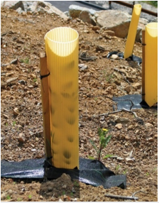
Figure 5-127 | Corrugated plastic tree shelter
Corrugated plastic tree shelters create a microclimate around seedlings to enhance moisture and temperatures for seedling growth. In addition, they protect plants from animal browsing. Photo credit: David Steinfeld
Tree shelters are translucent plastic tubes that are placed around seedlings after planting (Figure 5-127). They benefit seedling establishment by creating a favorable growing environment while shielding the seedling against animal damage. Tree shelters enhance plant growth by creating a microclimate similar to a mini-greenhouse, which has lower light intensities, higher temperatures, and higher relative humidities (Applegate and Bragg 1989; Jacobs and Steinbeck 2001). On high elevation sites, tree shelters increase above-ground temperatures and extend the growing season (Jacobs and Steinbeck 2001). Seedling survival and growth are enhanced by tree shelters on some sites because increased condensation on the inner shelter walls during the evening drips into the soil and increases soil moisture (Bergez and Cupraz 1997). On windy sites, tree shelters protect seedlings from wind damage and blowing sands (Bainbridge 1994). In addition, tree shelters protect seedlings from large game, gophers, rabbits, voles, and grasshoppers (Tuley 1985; McCreary and Tecklin 1997; Jacobs and Steinbeck 2001).
Where to Use—Tree shelters can be considered for sites where the potential for animal damage is extreme and seedling survival and rapid seedling growth are essential. These sites include, but are not limited to, sites with the following characteristics:
- Gopher or vole damage
- High elevation
- High winds
- Hot and dry
- High solar intensity
- Low water-holding capacity soils
- “One-shot” planting
Drawbacks—Tree shelters are not intended for all species or site conditions. Several studies have shown that, under certain climates, seedlings grown in tree shelters are more susceptible to low temperature extremes than those grown in the open (Svihra et al 1993; Kjelgren et al 1997). These conditions occur in the late winter and early spring on some sites when warmer daily temperatures in tree shelters induce earlier bud break and stem dehardening, leaving seedlings more susceptible to cold temperatures. Air temperatures can also be colder at night in tree shelters on some sites because tree shelters can potentially trap cold air near the ground surface (Swistock et al 1999). On the opposite extreme, extremely high temperatures in the summer can be reached inside the shelters during mid-day, which might be detrimental to seedling growth. For these reasons, knowledge of the effects that the shelters will have on each species to be planted and the climate of the site is important when installing tree shelters. Small trials, prior to installation, can point out potential problems.
In visually sensitive areas, tree shelters do not blend well with natural backgrounds. Depending on the species and the site, tree shelters might have to remain around plants for up to five years. In addition, long-range planning for shelter removal is critical; without removal, the stem of the plant can be restricted.
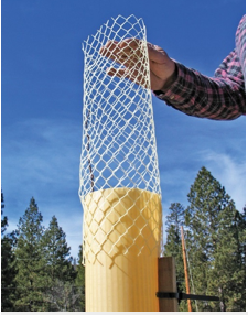
Figure 5-128 | Rigid tubing tree shelter
Rigid tubing can be installed over the top of the tree shelter to protect seedlings from larger browsing animals. Photo credit: David Steinfeld
Installation—Installing tree shelters may be done during or immediately after planting to protect seedlings from animal damage. Tree shelters are usually delivered in stacks of plastic sheets. They are assembled on site into cylinders that are placed over the seedling and held upright with a stake (Figure 5-127). The stake is driven into the soil so that the bottom of each cylinder is in direct contact with the soil surface. If burrowing animals are a problem, shelters can be installed several inches below the soil surface. This is an effective control of gophers and voles (McCreary and Tecklin 1997; Jacobs and Steinbeck 2001). Netting is sometimes placed over the opening of the shelter to prevent birds and lizards from becoming trapped (Bainbridge 1994). Rigid tubing can be placed over the top of the tree shelter to protect the emerging foliage from deer and elk browse (Figure 5-128). Tall tree shelters need very strong stakes anchored firmly in the soil to withstand strong winds. As the shelters are installed, it is important to take care to avoid skinned bark, damaged buds, or broken leaders. Where moisture is a limiting factor, weeding the vegetation from around the shelters is essential. Seedlings competing with weeds are unlikely to take advantage of the water saved by a tree shelter (Bainbridge 1994; McCreary and Tecklin 1997).
Maintenance and Removal—Installed properly, tree shelters usually require little maintenance. Nevertheless, it is good practice to inspect sites where tree shelters are installed annually to assess seedling conditions in the tree shelter and determine if any maintenance is needed. Because yellow jackets and other animals create homes inside tree shelters, it is wise to be cautious when conducting inspections.
Tree shelters create growing conditions that favor seedling height growth over stem diameter growth (Figure 5-129). Because tree shelters physically support the seedlings while they are growing, the seedling directs more of its energy into growing up to the light and less into the stem. It is practical to leave tree shelters in place until a portion of the seedling crown has grown out of the shelter. If the tree shelter is removed while it is still growing inside the shelter, the seedling will not be capable of supporting itself. Once the seedling has emerged from the shelter, stem diameters will continue to increase as the foliage acclimates.
Available Products—Tree shelters are available in a variety of shapes, sizes, colors, and styles from companies that specialize in reforestation, restoration products, or grape growing.
Color—Color and translucency of the plastic are important characteristics for selecting a tree shelter. Brown-colored tree shelters greatly reduce solar radiation and, in one study on a high elevation site, were shown to drastically decrease seedling survival of Engelmann spruce (Picea engelmannii) (Jacobs and Steinbeck 2001). On hot, dry sites, however, reduced radiation might benefit seedlings. Oak seedlings (Quercus spp.) planted in a semi-arid environment performed best in short, brown-colored shelters because of reduced daily temperatures (Bellot et al 2002).
Lighter-colored tree shelters allow greater solar radiation to reach the seedling but can also heat up when they are exposed to direct sunlight. Highly translucent tree shelters can be considered where light is limiting. Low translucent shelters might be more appropriate for sites where solar radiation and mid-day temperatures are high in order to reduce the potential for overheating.
Material—Tree shelters are made from translucent plastic for light transmission and are built with different degrees of sturdiness. Corrugated tree shelters are the sturdiest and are used on sites with strong winds. Corrugated materials are also used in taller tree shelters for added support (Figure 5-127), and thin plastic can be used in shorter shelters. Tree shelters are typically designed to degrade in five years, but in many cases they do not. Many shelters can therefore be reused, which will reduce project costs.
Ventilation—Without ventilation, tree shelters will build up heat on warm days, especially if they are in direct solar radiation. Maximum daily summer temperature in shelters can be 8 to 16 degrees C (15 to 30 degrees F) higher than ambient air temperatures (Steinfeld 2005). Extreme temperatures can be reached on days where ambient air temperatures exceed 38° C (100° F). For these sites, it is helpful to use shelters with some form of ventilation, such as holes. Ventilated tree shelters have been shown to reduce maximum daily shelter temperatures by 3° C (5° F) (Swistock et al 1999). Where ventilation is needed, taller shelters will likely require more ventilation than shorter shelters.
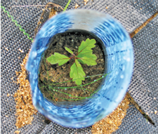
Figure 5-130 | Tree shelters and germinating seeds
Small tree shelters can be placed around germinating seeds to enhance germina¬tion and early seedling establishment, as shown in this photograph of an es¬tablishing California black oak (Quercus kelloggii) seedling in a tree shelter made out of xray film. Photo credit: David Steinfeld
A ventilated tree shelter may restrict carbon dioxide in the area around the seedlings, which would be a further consideration for ventilation. Some studies have shown that carbon dioxide is very low in shelters (Dupraz and Bergez 1997). However, other studies that have shown higher levels of carbon dioxide within shelters than outside (Frearson and Weiss 1987).
Size—The size of the shelter selected is based on the anticipated growth rates of the species planted and the anticipated animal damage. Shelter heights range from 1 to 9 feet and diameters up to 6 inches. To obtain the greatest benefit from tree shelters, it is good practice for the shelter height to not exceed the maximum seedling growth in the first year. Fast-growing species can have tall shelters; shorter shelters can be used for slow-growing species. Ideally, the shelter height would be greater than the browsing level of the foraging animal. For example, tree shelter heights in deer browse areas are most effectively used when they are at least 4 feet tall so that new seedling growth from the top of the tube is not severely browsed back. Extending the protection of the tree shelter can be done by using a rigid netting placed over the top of the shelter. Large shelters can be cut into any height or diameter needed for the project. Very small shelters (less than 6 inches tall) can be used around germinating seeds to protect them from small animals and create a micro-climate for germination (Figure 5-130).
Costs—Tree shelters can be an expensive addition to a revegetation project. The high costs to purchase, assemble, install, maintain, and remove shelters are considerations to balance against the benefit of increased survival and growth. On projects where smaller, less expensive seedlings are being planted, the cost savings from not planting larger stock can offset the installation of tree shelters. Assuming that tree shelters increase seedling survival, fewer seedlings would need to be planted, and these savings could offset the costs of installing tree shelters. Where quick establishment of vegetation is the objective, the use of tree shelters should be considered.
5.5.5 IRRIGATION
For the Designer
Shallow-rooted species such as grasses and forbs often require water near the soil surface and irrigation practices that provide water to this shallow area.
A wide range of irrigation methods and techniques are available to the designer, ranging from simple to elaborate, and from modestly priced to costly. Irrigation is often a very expensive component for most revegetation projects. For this reason, it is important to integrate the decision to irrigate, and subsequently the selection and design, with the objectives of the road project during the planning stages. The most common reason for irrigating in the western United States is to aid in seedling survival during the first several growing seasons. Those sites that have low soil water-holding capacities, high evapotranspiration rates, or low summer rainfall meet these criteria. Irrigation is also used when the project objectives call for a quick establishment of vegetation for visual screening, erosion control, or slope stabilization. Roadside irrigation is almost always a temporary measure, often spanning a maximum of three years. Therefore, elaborate or expensive irrigation systems are not often the best choice for these situations. Low-tech systems, requiring minimal maintenance, tend to be more appropriate for wildland restoration.
For the Designer
Deep-rooted species such as trees and shrubs often require water well below the soil surface where the roots are growing. Successful approaches to irrigating these species delivery water deep under the soil surface (see below).
The challenge in wildland irrigation is the timing and placement of water in the soil. An irrigation system that delivers water when the plant is less likely to need it is wasteful and can be detrimental to the seedling. A system or schedule that applies water when the plant requires it for survival or growth is most cost effective and beneficial for seedling survival and growth.
Developing irrigation schedules based on plant needs is an essential part of using irrigation for establishing plants, and those needs change based on the species being established, nursery stocktype, soils, and climate. Supplemental irrigation strategies are tailored to the vegetation requiring irrigation. For example, during prolonged drought, areas seeded with forbs and grasses may require supplemental surface irrigation whereas tree seedlings may require deep watering. Within a larger revegetation project specific plantings may require supplemental irrigation because of site-specific characteristics such as topography. For example, plantings in fast-draining areas such as ridgelines or wares with shallow soils may require more irrigation than plantings in the bottom of swales were water naturally collects.
Placing the water in the soil profile where it can be directly accessed by much of the root system is critical for efficient use of an irrigation system. Some irrigation systems moisten more of the soil profile than will be accessible by the establishing root system, and water is consequently wasted. Other ineffective systems barely wet the soil surface, leaving the applicator satisfied but the roots without water. The objective of an efficient and effective irrigation system in wildland settings is to deliver only the amount of water needed, when and where it is needed for seedling survival and growth.
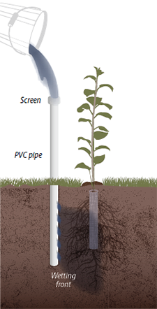
Figure 5-131 | Deep pot irrigation
Deep pot irrigation uses an open ended PVC pipe placed next to a planted seedling. Small holes (1 mm) are drilled 2 to 3 inches down the pipe and positioned to- ward the root system. A screen is placed over the top of the pipe to keep animals out. The size of the pipe and placement are designed to deliver the appropriate amount of water to actively growing roots (modified after Bainbridge 2006b).
Tree and shrub seedlings survive by growing roots down into the soil profile to access moisture at deeper portions of the soil profile than annual grasses and forbs. Deep placement of water for these species is far more important than surface soil moisture. In spite of this, many irrigation systems, such as drip, basin, and overhead sprinklers, deliver water through the surface, wetting soil where it is not needed and encouraging weeds and other competitive plants to establish and thrive. Furthermore, surface irrigation does not always ensure moisture will be evenly delivered to the deeper portions of the soil where the roots of trees and shrubs are growing. Soil structure and texture affect the wetting-front patterns of surface-applied irrigation water. If the soil is compacted, the amount of water that is delivered to the lower rooting zone can be reduced. A better method of water delivery to the root zone of trees and shrubs is to bypass the surface of the soil completely.
Deep Pot Irrigation
Several irrigation methods have been developed for arid land revegetation that bypass the soil surface and deliver water directly to the root zone. These systems include deep pot, porous hose, and wick irrigation methods (Bainbridge 2006a). Because these systems deliver water directly to the soil profile where roots are actively growing, far less water is required. Deep pot irrigation (Figure 5-131) appears to be the most effective and practical method for irrigating planted seedlings in arid environments (Bainbridge 2006b). This system has been found to be three times more effective at increasing seedling survival than surface irrigation using the same amount of water (Bainbridge et al 2001).
Deep pot irrigation delivers water to the root system through a pipe positioned next to the seedling (Figure 5-131). The pipe is either filled periodically by hand or through an installed drip irrigation system. The soil is moistened as water drains through both the bottom of the PVC pipe and the holes drilled in the sides. The amount of water delivered to the soil depends on the size of the pipe and how much water is applied. Deep pot irrigation pipes are typically made from PVC pipes, although most pipe or tubing material can be used. Pipe diameters range from 0.5 to 3 inches. Pipe lengths range from 8 to 18 inches, depending on the stocktype and water volume to be delivered. A seedling with a short root plug will likely require a shorter pipe, whereas a longer root plug will likely require a longer pipe. When properly positioned, the bottom of the pipe will be no deeper than the length of the root plug so the wetting front moves around the bottom and lower portions of the plug where it can be accessed by new, advancing roots. The top of the pipe is screened to prevent animal entry and is placed several inches above the level of the soil.
The diameter of the pipe will determine the quantity of water that can be delivered at any one irrigation (Figure 5-132). Given the same pipe lengths, a 2-inch-diameter pipe holds 4 times the amount of water as a 1-inch pipe, and a 3-inch-diameter pipe holds 8 times the amount of water. Because filling pipes is expensive, determining the proper diameter is important. Oversized pipes will deliver a wetting front that extends beyond where it can be accessed by the root system and water will be wasted. Pipes that are too small will not fully wet the area around the advancing rooting zone, requiring more frequent irrigations. Pipe size and irrigation frequencies depend on the factors described below.
Soil Type—Sandy or rocky soils have low water-holding capacities, causing wetting fronts to travel deeper and in a narrower band. Less water but more frequent irrigations are needed in these soils. Placing pipes closer to the root plug can ensure the wetting front reaches the root system. Finer textured soils, such as loams and clays, have a higher water-holding capacity and wider wetting fronts. More water can be applied in these soil types and at less frequent intervals than with sandy soils.
Stocktype—Large stocktypes have greater root volumes and greater above-ground vegetation to support than smaller stocktypes; therefore, they likely require more irrigation water. However, smaller stocktypes could require more frequent irrigation.
Seedling Quality—Healthy seedlings grow new roots quickly and can access deeper soil moisture. Poor quality seedlings are slow to initiate roots and therefore need to be irrigated more frequently.
Competing Vegetation—Where undesirable vegetation is growing near planted seedlings, soil moisture is depleted sooner, requiring more frequent irrigation than if seedlings were free from competing vegetation.
Species—Every species has unique rooting patterns, growth rates, and water needs. Those that grow roots quickly and have a higher rate of water withdrawal could require larger, deeper pipes and more frequent irrigation. These species include many fast-growing riparian species such as cottonwoods, willows, and maples. For more information, contact the nursery manager growing the species of interest. They are familiar with root growth and water needs by species.
The volume of the pipes and frequency of irrigation will determine the type of water delivery system to use. Sites that need frequent irrigation and high volumes of water per plant could require water delivery through a drip system (Section 5.5.5, see Drip Irrigation). For most projects, however, pipes can be economically watered by hand using backpack spray equipment or fire bladder bags. Bladder bags hold approximately 5 gallons of water and can be filled from water trucks or large water
containers positioned in pickup beds. Assuming that an irrigator can carry 20 quarts of water at a time (5 gallons) and each plant in the project requires a quart of water, the applicator could irrigate 20 seedlings before returning for more water. If less water is required, more plants could be irrigated before refilling is necessary.
Deep pot irrigation allows for the introduction of soluble fertilizers (Section 5.2.1) and mycorrhizal fungi inoculum (Section 5.2.7) if seedlings require these treatments. Because soluble fertilizers are delivered directly to the roots bypassing the soil surface, weeds are not encouraged to grow. It is important to take care when determining fertilizer rates to avoid increasing soluble salts above levels that are toxic for root growth. Monitoring salt levels and pH of the irrigation water can ensure that salts do not exceed toxicity levels for plant growth (Section 3.8.4).
Determining when to irrigate can be based on the plant moisture stress (PMS). An accurate method for determining PMS is using a pressure chamber (Inset 5-23). This equipment reads plant stress (in negative bars) at the time of the readings. The most effective PMS readings are made in the early morning, prior to sunrise, when diurnal PMS is at its lowest. It is good practice to collect five seedlings in one area and averaged per site. If pre-dawn PMS readings are less than -15 bars, seedlings are under high moisture stress and need to be irrigated soon to keep the seedlings from dying. If the objective of irrigation is for fast seedling growth, then PMS during plant growth (spring and fall) is best kept above -5 bars. PMS equipment is expensive to purchase. However, many USFS district offices use and maintain this equipment.
Inset 5-23 | Measuring plant moisture stress
Modified from McDonald 1984
Measuring plant moisture stress (PMS) with a PMS meter (A) is an accurate method to help determine the water needs and status of a plant. When a seedling is under moisture stress, it is pulling water from the soil through the stem. The water in the stem is under tension, much like a rubber band that is being stretched (B). When a small branch is cut, the tension in the stem is released and the water shrinks back from the cut surface (C). The further back the water shrinks, the more moisture stress the plant is under. The cut end of the stem is placed through a small hole in a stopper, with the end protruding from the lid (D). The foliage is placed in the steel chamber and tightened so it is airtight (E). Nitrogen gas is slowly applied into the chamber, exerting pressure through the stomata and pushing water through the stem toward the cut end. When the water just begins to emerge from the cut end, a pressure reading is made. This is the amount of suction or stress that the seedling is under at the time the sample was collected. Because PMS varies throughout a 24-hour period, the most useful seedling samples are taken in the pre-dawn for consistency and comparison purposes.
PMS readings can be used to determine when to irrigate seedlings. If pre-dawn PMS readings are greater than -15 bars, seedlings are under high moisture stress and need to be irrigated soon to keep the seedlings healthy. If the objective of irrigation is for fast seedling growth, then PMS during the plant growth (spring and fall) is best kept below -5 bars. PMS equipment is expensive to purchase; however, many USFS district offices use and maintain this equipment.
Photo credit: Thomas D. Landis
Drip Irrigation
Drip (or low pressure) irrigation is generally a temporary measure to help establish roadside plantings. It is typically used for one or two seasons to establish nursery-grown plants and then removed. Setting up drip irrigation might be considered extravagant. For projects where there is no tolerance for seedling failure, this can be a viable, economical alternative (Bean et al 2004).
Some advantages of using drip systems for roadsides are water efficiency, system flexibility, portability, and ease of application of soluble fertilizers. The main disadvantage is the high maintenance required to keep the system operational. Drip systems are composed of numerous points where failures can occur: storage tanks, burst end clamps, connectors, emitters, and hundreds of feet of pipe and drip irrigation tubing. For this reason, it is important to inspect and maintain the system regularly during the summer to ensure that all seedlings are being properly irrigated. This involves inspecting all emitters, pipes, tubing, and tanks. Emitters clog with sediment and insects (Bainbridge 2006c); animals gnaw through tubing when it is above ground; and plastic water tanks make great shooting targets. It is recommended that these types of damage to the system be repaired before each irrigation cycle. On hilly sites, the system needs to be designed to maintain the correct pressure to each emitter.
In its simplest form, the drip irrigation system consists of a water source, mainline and side lateral pipes, and drip pipes and emitters. Frequently, drip irrigation systems will have pressure reducers that regulate head-gain pressure. The pressure reducers are inexpensive and are available in many sizes that can be matched to the system emitters. The system is under pressure during irrigation, which moves water from the water source, through the mainline and side laterals, to the emitters where seedlings are watered. The objective is to deliver equal amounts of water to each seedling. This is not a problem when the system is laid out on flat ground and pressures at any point in the system are equal, but flat terrain is seldom found on highway projects. On projects that have any slope gradients, there will be changes in pressure depending on the elevation of the emitters. The pressure change occurs at a rate of 1 lb/in2 (psi) per 2.31 feet elevation drop. This means that an emitter at an elevation that is 46 feet lower than the water source will have a psi of 20 (46 / 2.31 = 20), while an emitter at 92 feet lower than the water source will have a psi of 40 (92 / 2.31 = 40). Unless pressure-regulating techniques are used to reduce the pressure to the lower elevation emitters, the amount of water delivered to those emitters will be approximately twice that of the upper elevation emitters. Compensating for pressure changes is critical for delivering equal amounts of water to each seedling. Systems that do not compensate will have seedlings that receive too much water, while others will not receive enough during an irrigation cycle.
Water Source—The water source constitutes the beginning point of the drip system. It is typically the most uphill point because it needs to feed every emitter below. Water is typically trucked to the site and pumped directly into the mainline or stored in temporary, portable storage tanks (Figure 5-133). Water trucks range in capacity from 1,000 to 2,500 gallons. If there is a location for a portable water storage tank above the planting area, gravity feed can be used to pressurize the system. Operational water pressure for a drip system ranges from 20 to 40 psi. To achieve a minimum pressure of 20 psi with a gravity feed system typically requires a 46-foot elevation drop from the storage tank to the first line of emitters (20 * 2.31 = 46). If this drop does not exist, then a pump will be needed to augment the pressure.
Components of a temporary water tank system include filters, on-off valve, and an inline pressure-reducer (if the water source pressure is greater than 40 psi) (Stryker 2001). When planning water storage, ease of access is an important consideration. Sometimes water will need to be pumped a substantial distance to a water storage tank. In other cases, more than one tank may be required to reach all planting areas in complex terrain. Water from unknown sources needs to be sent to a qualified lab and analyzed for contaminants and impurities (Zoldoske 1998). Chances are that most water sources will have impurities that will clog very small drip emitter openings. Installing a 100 (150 micron) to 150 (100 micron) mesh filter is recommended (Stryker 2001).
Mainline and Laterals—The mainline delivers water from the water source to the lateral pipes. The layout of the mainline and laterals can compensate for pressure changes associated with hilly terrain. A series of parallel lateral lines can be laid out perpendicular to the slope gradient. Because each line is on the contour, there is no pressure difference between emitters within a line. Between lateral lines, however, there is change in pressure based on 1 psi per 2.31 feet of elevation drop. Placing a pressure regulator at the connection between the mainline and each lateral line can compensate for the pressure increase with elevation drop.
The drip tubing diameter determines the volume of water that can be carried in the lateral lines and the rate it will be delivered based on friction losses. A 2-inch pipe, for example, carries four times as much water as a 1-inch pipe, but the costs are correspondingly much higher. For long stretches, increased frictional losses inside narrow diameter pipes can cause inadequate water coverage. Increasing water pressures or increasing pipe diameters can compensate for this.
The carrying capacity is the amount of water that specific tubing can deliver under a specific line pressure. For example, 0.75-inch tubing has a carrying capacity of approximately 160 gallons per hour at a line pressure of 20 psi, whereas a 1-inch pipe has a carrying capacity of 370 gallons per hour at the same pressure. Charts are available that compare various tubing diameters, emitter outputs, and system pressures for determining the length of tubing. These charts can be referenced when designing an efficient drip system.
Emitters—From the laterals, water flows through a smaller diameter pipe to the emitter, which meters out water directly to the base of each plant. Emitters apply water to the soil surface without wasting water on the surrounding area, thus discouraging non-target species. When emitters are placed in a deep pot irrigation system, water efficiency is increased further because water is delivered directly to the roots. There are many types of emitters, but pressure compensating emitters work well on hilly topography because they are designed to discharge water at uniform rates under a range of water pressures. With pressure compensating emitters, a system at 15 psi would have the same emitter flow rate as a system at 45 psi (Stryker 2001).
These emitters are two to three times more expensive than non-compensating emitters. Emitters come in a range of flow rates, with the most common rates of 0.5 gallon/hour and 1.0 gallon/hour. Flow rate for the emitters is chosen based on soil texture, the water requirements of the plants, the water delivery capabilities of a system, and budget. Most designers agree that placing two emitters at each plant is better than one emitter with twice the output because the water distribution area will more closely match the rooting profile of the plant. Two emitters also offer backup should one of the emitters become clogged.
A good grasp of the soil drainage and water storage characteristics is necessary in choosing emitter capacity and duration of irrigations. Well-drained soils (e.g., sandy texture or high coarse fragments) need emitters with higher flow rates but shorter irrigation time. However, poorly drained soils (higher in clays or compacted) need lower output emitters and longer irrigations. The size of planting stock will influence the number of emitters and flow rates; the larger the planting stock, the longer the irrigation cycles and the more output emitters that are needed.
There are a limited number of emitters that can be installed on any one lateral line. For example, 0.75-inch pipe or tubing delivers approximately 160 gallons per hour. The number of emitters that can be installed on the line will vary by emitter output rates. Installing 0.5 gallon/hour emitters allows approximately 300 emitters (600 / 2 = 300) on the line. If two emitters were placed by each plant, 150 plants could be watered on a line. If the emitters were rated at 1.0 gallon/hour, then 75 plants could be watered.
Installation—The installation of a drip system involves placing pipe and inserting emitters. Tubing comes in rolls and is easiest to lay out like a wheel to keep kinks from developing in the line. Lateral tubing can be placed upslope from the plant, which will act like a stake should the tubing move downslope. Tubing migrates until it has been used for a while and may require periodic staking. When the main line and laterals are in their general locations, the system is filled with water to flush the pipes clean. The ends are clamped or plugged and then filled again. This will reveal whether there are any leaks or problems to fix before installing the tubing to the emitters. A pressure gauge can be used at this point to take readings across long runs within or between lateral lines to check consistency of pressures. This is the time to correct any problems. Puncturing tubing for emitters can be done when the system is charged with water so that adequate emitter flows and problems are seen immediately. Some designers choose to bury emitters below the soil surface to reduce surface evaporation. Losing visual inspection, however, usually outweighs the benefits of this strategy (Zoldoske 1998).
Operation—Prior to operating the drip system, consider flushing the system to eliminate any dirt that got into the piping during construction and cleaning filters. Check salt levels and pH of the irrigation water using a pH/conductivity meter to ensure that salts do not exceed the toxicity levels for plant growth (Section 3.8.4, see pH). Once these measures have been taken, the system can be opened and lines and emitters can be inspected. If emitters need cleaning, repair, or repositioning, it is done at this time. Tools and spare parts for the system are brought along and used where needed. When to irrigate can be determined through PMS monitoring (Inset 5-23). Determining the duration of the irrigation cycle can be done once or twice during the growing season through a visual inspection of soil profiles dug below several emitters. Observing the wetting front several hours after the system has been shut off will allow the wetting front time to have stabilized. The irrigation system can be used to train the plant to grow roots deep. Unless deep pot plants are used, new installations have plants with shallow roots and watering can accordingly begin by being frequent and shallow. Less frequent, longer duration watering can be transitioned to, allowing water to penetrate deeper into the soil. The surface soil will dry while deeper soil will remain wet and the plant roots will follow the water. The metering of the water is made easy with the use of inexpensive battery powered remote control valves and small and reusable solar powered controllers.
Back to top

