Roadside Revegetation: An Integrated Approach to Establishing Native Plants and Pollinator Habitat
CHAPTER 2 – Initiation
Table of Contents
2.1 INTRODUCTION
For the Designer
It is beyond the scope of this manual to cover all the specific procedures and processes for every agency involved in road projects. However, this chapter provides a general overview.
Incorporating ecological concepts into all aspects of road design, construction, modification and maintenance is a goal of the transportation community (National Research Council 2005; Forman et al 2003). The Federal Highway Administration (FHWA), state DOTs, and other federal, state, and county agencies that are responsible for road infrastructure all strive to achieve this goal. One successful approach for meeting this goal is to integrate issues of native plant revegetation (including protection of existing vegetation) into the larger design and construction processes of road projects. Revegetation planning is now an integral part of road planning and is an important aspect of road projects that can achieve a higher level of success and project benefits when incorporated early in project design. Experts recommend (as illustrated on the timeline Figure 2-1) that the implementation phase of revegetation begins while the overall project development process is still underway. Waiting until construction begins reduces the likelihood that locally-adapted native plant materials in the quantities needed will be able to be propagated in advance.
For the Designer
Incorporation of revegetation planning very early on in road project development can benefit project coordination, schedule, and budget.
To increase the opportunity for successful integration of revegetation issues within the overall road project, the designer of a revegetation plan can identify the cooperators and agencies involved, discover how their processes and timelines work, and coordinate at the appropriate times and with the appropriate people. The revegetation plan designer can add greater project value if involved in planning and construction processes whenever soil and vegetation disturbances are planned. Agency schedules, milestones, and budgetary issues are commonly defined in the planning process to effectively synchronize the revegetation efforts with road development and construction.
Road projects may be administered from local, state, or federal levels, or sometimes from a combination of all three levels. In terms of timing, road projects can be complex and span many years, whereas other projects are streamlined and on a compressed timeline. It is beyond the scope of this manual to cover all the specific procedures and processes for every agency involved in road projects. This chapter, however, provides an overview to successfully navigate the various processes for a project. Designer involvement and input is important from the inception of a project through completion. The earlier one can get involved, the more input provided. The preliminary steps for initial involvement include:
- Defining cooperators, processes, timelines, and milestones.
- Defining objectives: What is the project trying to accomplish?
This chapter provides an overview of each of these steps, followed by a discussion of typical road development processes that includes key points of involvement. This chapter also discusses the technical content, interpretation, and use of road project plans and views.
Back to top
2.2 PRELIMINARY TASKS OF INITIATION
Roadside revegetation is a complex process, frequently involving numerous agencies and individuals. Appointing a single designer to coordinate the planning, implementing, and monitoring/adaptive management of the revegetation aspects of the road project can help streamline revegetation coordination. Typically, the designer will be the responsible professional landscape architect or civil engineer who is in charge of sealing the revegetation documents and is directly involved with the design and supervision of others who are assisting in the preparation of the design documents. Depending on the training and expertise of the designer, the project scale, level of environmental impacts of the project, and level of political and public scrutiny, the designer and owner of the project are often best served by enlisting experts from other natural resource disciplines to help with the revegetation planning so that expertise in botany, plant genetics, horticultural practices, landscape architecture, soil science, engineering, hydrology, wildlife biology (including pollinator specialists), geology, and ecology is available for the project as necessary. Project quality and efficiency can be enhanced when the designer is the coordinator of the technical and organizational aspects of the revegetation project, as well as the contact between revegetation efforts and the other aspects of road planning and construction.
2.2.1 DEFINING COOPERATORS PROCESSES, TIMELINES, AND MILESTONES
Designer due diligence early in the project planning process includes identification of the reviewing agencies and individuals involved in the road construction project, along with their respective roles and responsibilities. It is especially important to understand: (1) who the actual decision-makers are, (2) who the land owning agency is, (3) who maintains the road and roadsides, (4) who will be carrying out the road construction project, and (5) who is funding the project. Sometimes, the actual decision-makers are not the same people who attend the design meetings. It can be important for the designer and design team to confirm the agency organizational dynamics and to get key design direction approvals in writing at the appropriate times in the planning and design process.
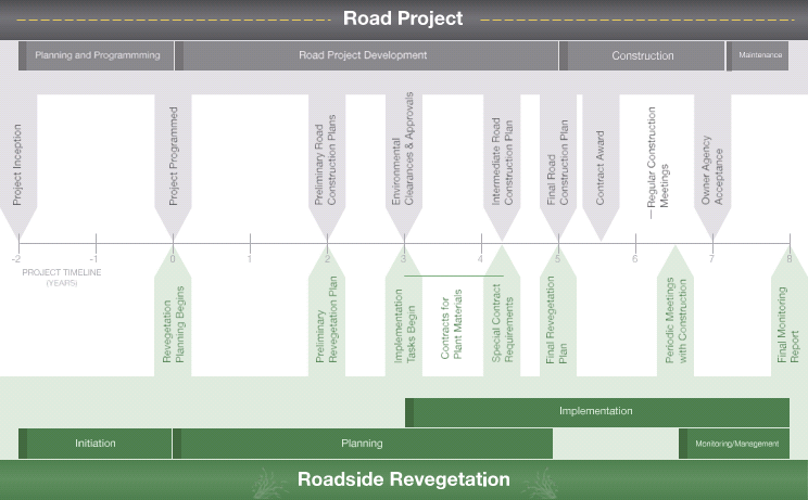
Figure 2-1 | Project coordination timeline example
Coordinating revegetation with the larger processes of road construction is helpful. While the timelines and agencies involved will vary, this figure illustrates some of the key opportunities for communication and integration.
An understanding that the timing, responsibilities, and, most importantly, the plan review and approval processes associated with each agency will vary, will allow the designer to plan, communicate, and interact more effectively with the right people at the right time. While this may seem complicated, many agencies have a procedural manual that describes how a project is carried out from conception to completion, defining the timelines, milestones, roles and responsibilities, terminology, and how funding works. Most current documents are online, however, some may only be available in hardcopy upon request. The designer may want to confirm the location of current documents with the reviewing agencies. Location and use of these documents and agency manuals to help create a project schedule can be a key due diligence item for the designer. Initial meetings with owners, maintainers, and agency plan reviewers are also beneficial for the designer, as they can create relationships that strengthen the lines of communication during the project, and are an ideal time to clarify project requirements, expectations, and various cooperator processes.
Each agency has certain approvals and procedural activities, including some that involve fulfilling environmental regulations. Early designer due diligence may include defining these activities and determining how revegetation work fits within them. The steps in the approval process are often important milestones for the agency, and they expect the designer to have that understanding and to provide input at appropriate times. Defining appropriate roles can help the designer to coordinate with the proper people, follow protocols, and avoid duplicating efforts.
Many variables affect the overall timelines from inception to construction. Timelines vary depending on the complexity of the project, the amount of controversy involved, and the availability of funds. Some projects take less than two years, while some can take over ten years. Reviewing Figure 2-1 with the assigned road project engineer and discussing milestones, timelines, procedures, budgets, and roles can be an effective approach to getting oriented to the complex process of road development.
2.2.2 DEFINING OBJECTIVES: WHAT IS THE PROJECT TRYING TO ACCOMPLISH?
Once the agencies and processes for each phase of the project are clarified, the designer can begin to understand how their work relates to the overall objectives of the project. Objectives can be found in the programming documents that originally identified the need for the project. These objectives often center on improving safety or updating the road infrastructure. Phase One of the planning process (Chapter 3) describes how to identify the objectives of the road project and translate them into specific goals for revegetation.
Environmental protection, pollinator habitat creation, and maximizing the ability of the roadside to regenerate native vegetation are primary revegetation goals. When a revegetation designer is involved early in a project, when disturbances to soil and vegetation are planned, the designer can be a key link to understanding the potential disturbances that might be caused and how to best minimize or mitigate them. The designer, with specialists’ input, can help the roadway engineer understand what types of disturbances can be feasibly revegetated with native plants. If a disturbance to soil and vegetation will not allow for revegetation, alternatives to that type of disturbance can be considered. The input of specialists can be crucial for determining potential strategies and alternatives. The project objectives also help determine the types of native vegetation that are most appropriate for the work. Revegetation design solutions can vary widely depending if the project crosses a wildlife corridor, is a scenic drive, is in an ecologically sensitive area with more intensive recovery needed, travels through open farm land, or contains steep slopes.
Safety, efficiency, protecting and enhancing environmental health, and creating habitat for pollinators are all important priorities in road projects. While safety concerns may at times limit what is appropriate in roadside revegetation (e.g., tall trees along a roadside may be a desirable choice from an environmental and aesthetic standpoint but not from a safety or visibility standpoint), experienced design professionals recommend that these concerns not be viewed as an impediment to successfully revegetating roadsides. Some experts recommend that the designer coordinate early with the roadway engineer to gain a full understanding of safety issues, particularly regarding visibility and the ability of drivers to recover if they drive off the road and into the roadside area (see discussion of how to define roadside revegetation zones in Chapter 3).
Back to top
2.3 THE PROCESS OF ROAD DEVELOPMENT
While each cooperating agency will divide up and define tasks differently, the process of road development generally has four stages: (1) planning and programming, (2) project development, (3) construction, and (4) maintenance. For revegetation work, the implementation phase often begins well before road construction is initiated (with the collection of plant materials for propagation). Revegetation efforts also continue after road construction is completed. Figure 2-1 compares the revegetation process with the overall road development process, showing process steps where interface is crucial.
During road project development, a number of meetings can take place involving representatives from the agencies and interests involved with the project. Experts recommend setting revegetation and wildlife objectives, such as developing pollinator habitat, accommodating wildlife corridor crossings, and planning stormwater features as habitat enhancement, early in the planning and programming phase, as they each have project safety, schedule, and budget implications. During the planning phase, meetings usually take place at the preliminary, intermediate, and final stages of the road plan. It is recommended that the designer attend these meetings. This ensures that good information gets into the project budget and schedule, that quality communication takes place, and that trust is built during the road planning process.
For the Designer
Providing wildlife crossings under roadways can increase driver safety. Planning and budgeting of wildlife under-crossings is often overlooked.
Meetings also offer the opportunity for reminders and confirmation that designers are meeting any requirements they face and that proper channels are utilized to get the job done. Regular communication between designers and quality control plan review at similar preliminary, pre-final, and final milestones can lead to developing a complete set of construction documents that can be easily interpreted and tightly bid. During the construction phase, the construction manager, design engineer, and other key players carrying out the project typically meet on a weekly basis. Attending some of these meetings can be valuable both for learning and contributing input as the project progresses, and for interacting with contractors, inspectors, and other stakeholders who may also be at the meetings or field site. Key contacts (such as the construction manager or design engineer) can help clarify the most appropriate meetings to attend, as well as the channels for communicating with other individuals who are involved with the project.
2.3.1 ROAD PLANNING AND PROGRAMMING
The process of deciding when to modify or build a section of road is often lengthy. Transportation planners identify and prioritize functional, structural, and safety issues regarding roads. If an issue is becoming problematic, alternatives to address it will be considered (FHWA 2005). The negative effects of transportation infrastructure and rights-of-way on communities and the environment are well documented. New road alignments or major road widenings are often controversial and often involve extensive study of functional, cultural, environmental, and aesthetic issues.
Context Sensitive Solutions (CSS) are design solutions, often developed through a public engagement process, that identify and address site-specific effects in an attempt to physically and visually connect transportation facilities into communities and their surrounding contexts. Depending on the project scope and context, solutions often prescribe bridge and wall structure aesthetic design, lighting and signage styles, bicycle, pedestrian and wildlife crossing accommodations, development of stormwater facilities as wildlife habitat, and providing appropriate types and amounts of vegetation. Each solution has function, safety, schedule, and cost implications for a project and are typically most successful when addressed early in the planning and programming of a road project. The revegetation design professional is often well-versed in Context Sensitive Solutions and can benefit the road project if their input is included in the early planning and programming phase.
The FHWA, several State DOTs, and several States have adopted policies to provide sustainable highway design, CSS studies, and incorporation of CSS solutions into their transportation projects. As examples, the framework to provide Sustainable and Context Sensitive Solutions is found in the State law and policy for both the Illinois DOT and the Indiana DOT. In the State of Illinois, Statute 605 ILCS 5/4-219 Context Sensitivity, states: “It is the intent of the General Assembly to ensure that Department of Transportation projects adequately meet the State's transportation needs, exist in harmony with their surroundings, and add lasting value to the communities they serve.” Statute 605 ILCS 5/4-219 also states that “A hallmark [of the context sensitive design process is to include]… early and on-going collaboration with affected citizens, elected officials, interest groups, and other stakeholders to ensure that the values and needs of the affected communities are identified and carefully considered in the development of transportation projects.” Further, the Illinois CSS process and design promotes “the exploration of innovative solutions, commensurate with the scope of each project that can effectively balance safety, mobility, community and environmental objectives in a manner that will enhance the relationship of the transportation facility with its setting” (State of Illinois General Assembly-a, 2013).
Similarly, the Indiana “Procedural Manual for Preparing Environmental Documents” (State of Indiana, 2008), includes section II.B.3.f, Context Sensitive Solutions (CSS), which states that “INDOT’s goal is to incorporate CSS into development, construction, and maintenance processes for improvements to the state jurisdictional transportation system.” The manual also states that “CSS promotes the following key principles:
- Use a full range of communication methods early and often, to effectively engage stakeholders and the public.
- Use interdisciplinary teams.
- Seek consensus on purpose and need.
- Document, track, and address all commitments.
- Use all resources effectively in the decision making process.
- Allow for design flexibility while considering a safe facility for all modes
Inset 2-1 | Roadside vegetation and driver safety
Greater safety for the traveling public is the primary objective of many road projects. The designer can support road safety when he/she does not propose vegetation strategies that might make the roadway less safe. Integrating revegetation goals with safety goals can meaning balancing an awareness of visibility issues, wildlife interactions, and other factors. Highway roadside design and revegetation efforts are subject to clear zone requirements that follow the American Association of State Highway and Transportation Officials (AASHTO) recommendations. FHWA and State DOT agencies are interested in the concept of a “forgiving” roadside: a roadside environment that allows a driver to recover safely if they drive off the road onto the roadside. The agencies expect a clear zone of low vegetation adjacent to the road, preferably low grassy surfaces, or shrub masses instead of trees. The roadside distance required to make a roadside forgiving depends on the speed limit of the highway, the traffic volume, and surrounding conditions. The AASHTO Roadside Design Guide (RDG) recommends clear zone widths based on the road design speed, average daily traffic, the up or down slope of the roadside and horizontal curve radius. The presence of curbs does not affect the clear zone distance along high speed roadways. Highway clear zones are generally are in the 20-46 foot range, but vary based on speed and noted conditions.
While the CSS process works to identify both broad and detailed impacts of a project and proposes appropriate mitigation and enhancements, the process also aims to accomplish the prime goal of the project and be sustainable over the long term. Sustainable design in the design-build environment seeks to balance environmental, functional and financial needs and impacts. All can be accomplished through thoughtful and efficient design that seeks to do no harm, minimize its footprint, and strives to incorporate dynamic functional solutions. Ideal sustainable design solutions often accomplish their intended function, are aesthetically pleasing, endure and improve over time, and reduce future costs and impacts.
Many DOTs have committed to utilize FHWA’s Infrastructure Voluntary Evaluation Sustainability Tool (INVEST). This tool facilitates the development and tracking of sustainability measures throughout a project’s life, including overall planning, project development, and operations and maintenance. A project is measured for “triple bottom line” Social, Environmental, and Economic accomplishments with the INVEST scorecard; for example, the Rural Extended Project Development module lists 25 weighted items on which the project can score. A “Platinum” rating is achieved when 60 percent or more of the possible sustainability rating points are achieved. More information on FHWA’s INVEST tool is available at the website www.sustainablehighways.org.
Design studies and tools such as CSS and INVEST attempt to create projects and budgets that address the “triple bottom line” for the benefit of the public and the environment. With or without these tools, wildlife corridor crossings and bicycle/pedestrian connections are two issue areas that are often overlooked when roadway budgets are initially set. The accommodations for wildlife corridors and bicycle/pedestrian connections through transportation routes are detailed functional, structural, and safety issue items, with significant project cost implications. Wildlife crossings can require taller bridge heights, longer spans, and may be needed at multiple bridges to accommodate safe movement of large animals across the right-of-way. Bicycle/ pedestrian connections can require wider bridges for bicycle lanes and sidewalks, protective medians or barriers, and may be needed over or under multiple roadway bridge structures. Ignoring these accommodations can have long-lasting functional, safety, and financial impact on communities, motorists, and wildlife.
Once it has been determined that a road will be built, modified, or updated, how it will be built or modified, and an alignment selected, a budget and schedule are created. At this point, the project has been “programmed” for a specific delivery year. This process usually identifies the following:
- Project purpose and need
- Roles and responsibilities of partnering agencies
- List of project alternatives established
- Primary contacts for project
- Preliminary project delivery schedule with milestones
- Collection and analysis of traffic data (accident history, average daily traffic volumes, etc.)
- Preliminary construction cost estimate
Environmental concerns for the project (cultural and natural resource) and estimation of the affected environment (WFLHD 2005).
Experts recommend that a revegetation designer be involved throughout the early planning and programming of a roadway project in order to identify issues and solutions, refine the budget, and help assess the feasibility of various alternatives.
2.3.2 ROAD PROJECT DEVELOPMENT
The road project construction (contract) document development process begins after the project is programmed and ends with the beginning of construction. Depending on environmental concerns and right-of-way issues, the project development process may take between one and five years. Contract documents are typically defined in the Owner-Contractor Agreement within the specifications Division 00. Contract documents typically consist of drawings, specifications, addendums to 100 percent documents distributed to bidders, and supplemental drawings provided by the designer to the contractor.
The road project development phase usually has three document review and approval sub- phases. These involve developing, analyzing, and considering approaches and alternatives to various design details within the project until a strategy and specifications of how to best proceed are shared in the final documents. The process usually involves:
- Preliminary—review of road construction documents that are approximately 30 percent complete
- Intermediate—review of road construction documents that are approximately 50 to 70 percent complete
- Final—review of road construction documents 70 to 100 percent complete. Final reviews often have a 95 percent or 100 percent pre-final review and the designer is able to make final corrections before plans are distributed for bidding or construction. Ideally, only the approved 100 percent plans will be advertised for bids and then given to the awarded contractor for construction or in a design-build process, the 100 percent plans will be reviewed and approved by the contractor and project owner team and construction will begin.
Preliminary Phase
The preliminary development phase involves collecting information and initiating contacts with “stakeholders.” Stakeholders are individuals or parties who are interested in or affected by the road construction (local and adjacent landowners, resource agencies, regulatory agencies, and any other potentially affected parties). The local jurisdiction will often be able to provide a detailed contact list of stakeholders who will likely be interested in the road project. The preliminary phase is necessary to refine purpose and need, to develop a range of alternatives to address purpose and need, and to obtain the approvals and clearances to allow the project to proceed. This includes commitments for CSS safety, cultural, aesthetic, functional, and environmental mitigations. The preliminary phase takes the road construction plans to about 30 percent completion. Once approvals and clearances are obtained, funds can typically be committed to continue development of the project.
Usually the preliminary phase will include the development and identification of:
- Preliminary construction plans (usually drafts about 30 percent complete) of the proposed alternatives (plan/profile sheets, typical sections, major work items identified and located)
- Preliminary construction cost estimates for alternatives
- Resource surveys (wetlands, archeological sites, and biological assessments)
- Preliminary construction schedule
- Identification of impacts and mitigation
- Environmental approvals and selection of alternatives for implementation
- List of contacts for the project
For the revegetation designer, the preliminary phase is a crucial one. This phase often represents the best opportunity for input regarding issues associated with revegetation, including disturbances planned for existing soil and vegetation on the site. Significant features of the preliminary revegetation plan will need to be incorporated during this road planning phase. By the time of environmental approvals, the vegetative concepts and the necessary commitments of resources and funds will need to be integrated with the documents, as revegetation is an important aspect of environmental protection and mitigation. The appropriate level of detail for the revegetation plan during the preliminary phase depends on the project. State and local agencies may specify environmental goals and requirements for the project regarding issues of soil stabilization, percent native vegetative cover, and protection of water quality (Inset 2-2). The designer is often asked to assist in preparation of the Storm Water Pollution Prevention Plan (SWPPP) for the project based on these goals, and to design them into the final revegetation plan. Environmental approvals are key milestones for the project team in order to maintain the project schedule, and for some designer teams, important in regard to availability of funds to carry out site assessments and revegetation planning work including preliminary mapping and seed collections.
Intermediate Phase
The next phase of road development moves towards 50 to 70 percent completion of the road construction documents. This phase involves refining plans and specifications, obtaining rights-of-way and permits, and creating detailed plan and profile sheets. The intermediate set of documents will include major budget items and quantities, final information pertaining to environmental concerns (such as SWPPP or erosion control plans), and major elements such as grading, drainage, and other issues defined.
At the intermediate stage, the designer is typically far along in the development of the revegetation drawings. The SWPPP is submitted to the State or local jurisdiction for review and approval. Mitigating measures have been identified for affected areas and owner or design-build contractor contracts for seed and seedling production have begun. The intermediate set of road documents will include specifications for how the road project will be carried out. These specifications and contract requirements are key tools for the designer.
For the Designer
Special Provisions and special contract requirements often need pre-approval by the reviewing agency prior to inclusion in construction documents. The approval process can take several months.
Special Contract Requirements: A Key Tool for Revegetation
In every phase of road development, there are two key components of contract documents: (1) drawings (plans) and (2) specifications (contract descriptions). The drawings are visual representations of the proposed work with dimensions, labels, and notes as described later in this chapter. Specifications describe and define materials, equipment, systems, procedures, performance, workmanship, standards, provisions, and requirements for the work that each agency provides to contractors or employees to carry out the work. A “special provision” (FHWA, State DOT) or “special contract requirement” (US Forest Service) is a type of specification. Standard specifications are uniformly carried out for most projects.
Special provisions or special contract requirements address local, project specific, context-sensitive concerns for a particular project. They are modifications of existing specifications found within the agency manual, or newly written specifications that are designed to address special concerns not adequately addressed in the standard contract specifications. For example, a standard specification may exist for chipping woody debris; however, the standard specification does not address size requirements of the chipped material. A project may require a uniform size of material be shredded and screened, rather than chipped, to create optimal mulch for the project. Accordingly, the designer can create a special provision or special contract requirement that will specify the size (such as three inches or less in length) and processing needs (such as shredded and screened rather than chipped). Careful research is often needed to adequately develop and describe a special provision or special contract requirement, and ultimately to achieve the desired results in the field. In the future, generically applicable special provisions or special contract requirements may become adopted as standard specifications if they come to be utilized on most projects.
Inset 2-2 | Example of an environmental regulation requirement
“Final stabilization” means that all soil disturbing activities at the site have been completed and that a uniform perennial vegetative cover with a density of at least 70 percent of the native background vegetative cover for the area has been established on all unpaved areas and areas not covered by permanent structures, or equivalent permanent stabilization measures.
“Final Stabilization” (adapted from EPA 2006) means that:
- All soil disturbing activities at the site have been completed and either of the two following criteria are met:
- a uniform (i.e., evenly distributed, without large bare areas) perennial vegetative cover with a density of 70 percent of the native background vegetative cover for the area has been established on all unpaved areas and areas not covered by permanent structures, or
- equivalent permanent stabilization measures (such as the use of riprap, gabions, or geotextiles) have been employed.
- When background native vegetation will cover less than 100 percent of the ground (e.g., arid areas, beaches), the 70 percent coverage criteria is adjusted as follows: if the native vegetation covers 50 percent of the ground, 70 percent of 50 percent (i.e., 35 percent (0.70 X 0.50 = 0.35) is total cover for final stabilization. On a beach with no natural vegetation, no stabilization is required.
- In arid and semi-arid areas only, all soil disturbing activities at the site have been completed and both of the following criteria have been met:
- Temporary erosion control measures (e.g., degradable rolled erosion control product) are selected, designed, and installed along with an appropriate seed base to provide erosion control for at least three years without active maintenance, and
- The temporary erosion control measures are selected, designed, and installed to achieve 70 percent vegetative coverage within three years.
Special provisions or special contract requirements are an important tool for designers to communicate special expectations with contractors, to clearly define contracting responsibilities to reduce duplicate efforts, and to set standards for performance. The designer can specify to contractors what the requirements are, and how they might be met, measured, and paid for. The agency with jurisdiction over the specifications will review and approve special provisions or special contract requirements and assign them specification numbers, a process that typically can take weeks or months. An effective practice can be to give attention to modifying or creating special provisions or special contract requirements to meet the revegetation needs of the project by the intermediate phase. Special provisions or special contract requirements that are approved may be included in the final contract documents for the road construction project.
Final Phase
The final set of road construction documents will include the detailed design elements of the Revegetation Plan, as well as all the details for road construction. Drawings and contract specifications will be fully developed. Special provisions and special contract requirements will have been submitted and approved. Environmental approvals and permits will have been accomplished. Final cost estimates will be provided along with a comprehensive schedule. The work of the designer in developing the revegetation plan, as well as efforts to reduce the construction footprint and protect native vegetation on the project site, will be an integral part of the road construction documents. At this point, the revegetation documents, including a budget, are finalized. Final road construction documents are submitted for distribution to bidders or, in the case of design-build, are submitted to the contractor who distributes them to his or her team of sub-contractors. Once the documents are in the contractor’s hands, there is a good opportunity for the revegetation designer to connect and coordinate with the contractor, landscape sub-contractor, and agencies in order to confirm plant material sources and to schedule availability of plant materials with outplanting windows.
2.3.3 CONSTRUCTION
Following project development, the construction phase begins. Road construction can take one to three years. Sometimes there is a formal milestone when the project is handed off to construction personnel. If so, the construction manager or project engineer becomes an essential contact for the designer, who may attend some of the weekly meetings that will take place during road construction. The construction phase of a road is completed when there is a formal acceptance of the road by the road owning agency. For the designer, implementation and monitoring phases of revegetation may begin before road construction (e.g., with plant materials procurement and continue following completion of construction.
2.3.4 MAINTENANCE
Following construction of the road, the work of the designer will usually continue for an additional one to three years until the revegetation is fully implemented. Also, the activities centered on monitoring and adaptive management of the establishing vegetation continue to take place, perhaps up to five years after the road construction is complete. The submission of a final monitoring report is the milestone marking the end of the designer’s formal efforts on the project. Although the designer’s efforts are contractually complete, valuable information can be obtained by periodic visits to the project site in order to see how the restoration efforts develop over time.
Coordination with the road owning agency and the individuals who carry out road maintenance is important to ensure that native vegetation continues to thrive on the site. In many instances once the state DOT hands off the project to the county, the state DOT does not provide further input. For example, the agency taking ownership, often the county, could have maintenance methods that may ultimately undo portions of the revegetation, such as blanket herbicide use as standard practice along roadsides. The designer can protect the revegetation plan by identifying the ultimate roadside vegetation management agency in the planning phase, checking what maintenance methods are currently utilized, and to continually coordinate efforts with the ultimate maintaining agency in order to ensure that future management is appropriate for the native vegetation. The transportation agencies can continue to monitor the road to ensure that the project adequately addressed the problem (infrastructure decay, safety issues, etc.) that led to it.
Back to top
2.4 ROAD CONSTRUCTION PLANS
This section explains how to use roadway engineering views for revegetation planning, including determining the vegetation zones that begin where the pavement ends. A glossary with illustrations is provided in order to understand technical concepts and terminology for effective communication with others involved in road design and construction. This section also describes how to read and interpret:
- Plan views
- Profile views
- Cross-section views
- Typical views
- Summary of quantities tables
The plan set consists of construction drawings and specifications for each section of road or project. The four most common views of plans utilized by the designer are plan views, cross-section views, profile views, and typical views. Each of these is defined in Table 2-1. Examples and descriptions for interpreting each of these views are provided below. Each engineering plan includes a legend defining abbreviations and symbols as well as a summary of plan quantities table.
2.4.1 PLAN VIEW
The plan view shows the existing and proposed road locations from a bird’s eye view. It is important to note that plan sets, in particular road plans, historically displayed distances in meters. This practice was discontinued nationwide in the early 2000s and distances are now displayed in US Customary Units (feet). The proposed road is usually designated with solid lines (Figure 2-2A). The solid centerline (of the road to be constructed) is divided into 100 foot sections (large ticks), often with 20 foot subdivisions also designated (small ticks—not shown). Each 100-foot division is called a station, representing a discrete, surveyed, and identifiable point within the road corridor. Each station is identified with a unique number that indicates its distance from the beginning of the project. For example, the station 19+000 indicates this point is 19,000 feet from the start of the project; 19+040 indicates this point is 19,040 feet from the start.
This short-hand identifier is also used to indicate the placement of road-related infrastructure, such as culverts, the beginning and end of guard-rail construction, or the placement of a sign. In the field, stations are identifiable as vertically aligned numbers written on wooden stakes and driven into the ground, facing the roadway. Detailed location of elements off of the roadway can then be identified by station along the centerline of the alignment plus the offset distance dimension from the edge of roadway pavement. This will appear as a +0.00 note on the field stake. Not only do the stations provide locations, they help to locate revegetation units. The plans also show the top of the cut slope (Figure 2-2B, dotted line), bottom of the fill slopes (Figure 2-2C, dashed lines), and the location of the original road, which will be obliterated in this example (Figure 2-2D, shaded area). Plans also include temporary construction easement lines (Figure 2-2D (outside line)) and right-of-way lines (ROW or R/W). These are, in effect, the property lines of the roadway and an important boundary for the designer.
Table 2-1 | Definitions of views
View |
Definition |
Plan |
A drawing depicting a portion of the road project from a bird’s eye view. |
Profile |
A drawing depicting the vertical plane section along the longitudinal centerline of the road, expressed in elevation or gradient. |
Cross-section |
A drawing depicting a horizontal section of the road viewed vertically, as if cut across the width of the road. |
Detail |
A drawing depicting features of a particular design, installation, construction or methodology. |
Source: Keller and Sherar 2003 |
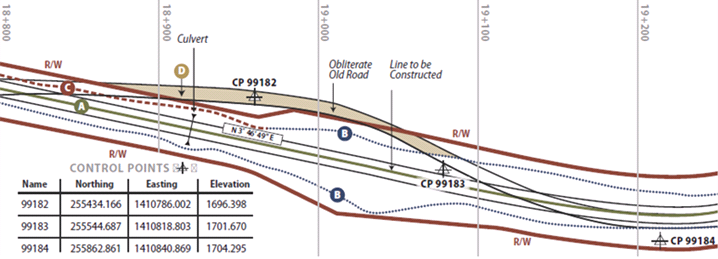
Figure 2-2 | Example plan view
2.4.2 PROFILE VIEW
The profile view is a trace of a vertical plane intersecting a particular surface of the proposed road construction (Figure 2-3E). It corresponds to the longitudinal centerline of the road bed in the plans. Profile grade means either elevation or gradient of the trace, depending on the context. The trace of the existing road is shown as a dashed line (Figure 2-3F) and a dotted line (Figure 2-3G). A vertical scale provides useful information about the profile of construction grades throughout the project. This view shows where the proposed road will be lower than the existing road (Figure 2-3H) and areas where it will be higher (Figure 2-3 I). Where the planned road is lower, material will usually be removed and used in areas needing fill. Additional information is often displayed adjacent to and locatable by the station numbers, such as volumes of excavation and embankment work, guard-rail placement, or wall placements.
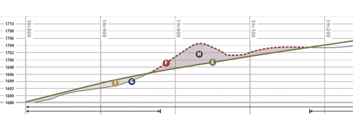
Figure 2-3 | Example profile view
2.4.3 CROSS-SECTION VIEW
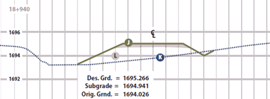
Figure 2-4 | First example cross-section
Cross-sections are views of the slopes perpendicular to the direction of the road. They display a vertical section of the ground or structure at right angles to the centerline or baseline of the roadway. Depending on the length and topographic complexity of the road, there can be hundreds of cross-sections. Each cross-section is referenced back to a station. For example, the cross-section shown in Figure 2-4 depicts the slope at Station 18+940. It shows the proposed road (Figure 2-4 J), and the natural ground line as a dotted line (Figure 2-4 K). This section will have material brought in and placed as fill (Figure 2-4L).
The cross-section in Figure 2-5 shows a through cut at 19+000. Material will be removed from the natural ground line (Figure 2-5K) to the proposed ground line - solid line (Figure 2-5 M).
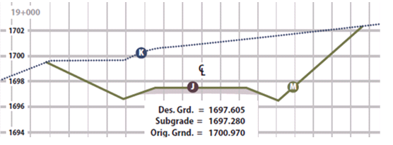
Figure 2-5 | Second example cross-section
Cross-section and plan views are used together to view the proposed road three-dimensionally. From these views, a more detailed revegetation plan can be developed. Each cross-section can be reviewed and a set of revegetation criteria can be developed for similar cross-sections throughout the project.
Cross-sections show the proposed slope gradients for cut and fill slopes and provide the designer a means to determine slope steepness. Like stationing, the method of depicting slopes has changed over the years. Older plan sets often depicted slopes as a ratio of one unit horizontal to one unit vertical. Several years ago, however, slope ratios were brought more in line with other disciplines and are now depicted as one unit vertical to one unit horizontal (vertical:horizontal). When slopes are flatter than 1:1 (45° or 100 percent), the slope is expressed as the ratio of one unit vertical to the number of units horizontal. For slopes steeper than 1:1, the slope ratio is expressed as number of units vertical to one unit horizontal. To avoid confusion, it is wise to notate the ratio by indicating the vertical and horizontal, for example 1V:2H, and to think in terms of rise over run (Figure 3-61).
2.4.4 TYPICAL VIEWS
Typical views graphically illustrate the design or construction details of the structures or other components that will be encountered in the road project (Figure 2-6). They can cover such structures as retaining walls, road surfaces, guardrails, ditch lines, plant installation, etc. They may be shown in profile, cross-section, or plan views (Figure 2-7). Like special contract requirements (see above), typical views are useful in helping communicate a new or modified approach to an existing methodology or construction technique.
2.4.5 SUMMARY OF QUANTITIES TABLE
Tabulation of plan quantities tables contain details on quantities, types of materials, and performance specifications. Standardized for Federal Lands Highway projects, specifications for construction of federal roads are described in the FHWA handbook: Standard Specifications for Construction of Roads and Bridges on Federal Highway Projects. They are cited as “FP-03,” or “FP-14”, indicating “Federal Project” specifications issued in 2003 or 2014, respectively. The State DOTs have analogous manuals. Tabulation of plan quantities references not only the particular item specification number in the FP manual, but also the station number(s) of the planned work. Information of special interest for the designer includes the number of hectares of clearing and grubbing, hectares of obliterated roads listed by station, and the number of cubic meters of wood mulch to be produced. The summary of quantities table provides a summary of all tabulation of plan quantity tables contained within the plan. It generally does not include station numbers.
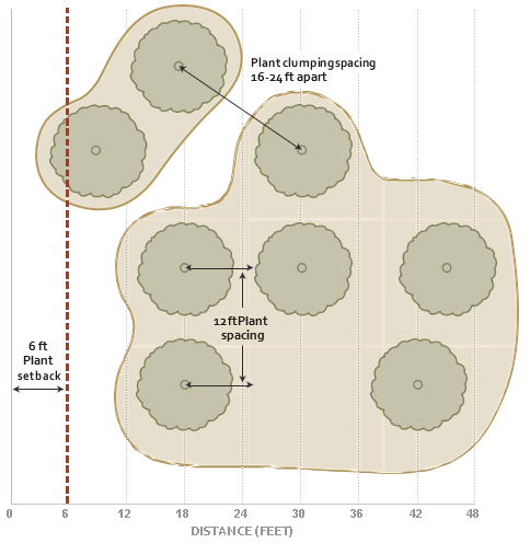
Figure 2-6 | Example typical view
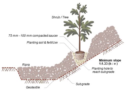
Figure 2-7 | Example typical view of installation trail and turnout
Back to top
2.5 INTERPRETING ENGINEERING VIEWS FOR REVEGETATION PLANNING
Road construction, management, and safety concerns result in distinct revegetation zones along roadsides. Properly interpreting plans helps define where these zones may be located and what types of vegetation should be established. While the sizes and characteristics will vary, the zones that parallel the road can be grouped into four categories. Zone 1 begins immediately adjacent to the road surface (concrete or asphalt) and includes the road shoulder (concrete, asphalt, compacted gravel, coarse subsoil, etc.), the bottom of the drainage ditch, and portions of cut and fill slopes. This first zone is generally considered to be up to 10 feet from the pavement edge and is often barren of vegetation due in part to herbicide application, road salts, frequent ditch cleaning, and/or mowing. Local, state, and federal road managing agencies will have limitations to the types and proximity of vegetation that can be established next to the road. Zone 2 begins at roughly 10 feet from the pavement edge and continues laterally to about 30 feet. This zone may begin at the ditch bottom or at some point on a cut or fill slope, and may continue to the limit of the construction zone. Within Zone 2, grasses and forbs can thrive, but larger forbs, shrubs, and trees usually are not planted or encouraged due to safety, maintenance, and visibility issues. Beyond 30 to 50 feet from the pavement edge, Zone 3 begins in which larger forbs and shrubs can be planted. Past about 75 feet from the pavement edge, Zone 4 begins with largely unrestricted revegetation potential. Understanding these zones is necessary to coordinate revegetation with road management practices and safety considerations (Forman et al 2003).
To define the zones and begin to interpret engineering plans for revegetation work, information from plan sheets and quantity tabulations is applied to the plan map as shown in Figure 2-8. Each area can be considered a revegetation unit or subunit. An estimate of the area in each of these units can be calculated and used in determining how many seedlings or pounds of seeds will be needed. These criteria can be graphically displayed on a typical cross-section (Figure 2-9). On this cross-section, the criteria can be expressed as follows: from 20 to 60 feet grasses/forbs will be hydroseeded; from 60 to 100 feet shrubs will be planted; and on obliterated roads, trees will be planted. The slopes given in cross-sections can help define the types of revegetation methods available.
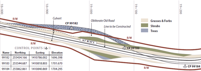
Figure 2-8 | Interpretation of plan view showing revegetation zones
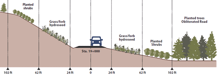
Figure 2-9 | Cross-section showing revegetation zones as interpreted from engineering plans
Back to top
2.6 UNDERSTANDING TECHNICAL CONCEPTS AND TERMINOLOGY
The ability to understand and utilize the technical concepts and terminology used by road engineers is essential to roadside revegetation planning. This ability enables the designer to contribute effectively to road design and construction processes, as well as to communicate revegetation needs and goals to others involved with the project. The following section introduces key technical concepts and terminology relating to road design and construction
Road Concepts and Terminology
The following terminology was adapted from Keller and Sherar 2003.
2.6.1 ROAD COMPONENTS
- Berm—A ridge of rock, soil, or asphalt, typically along the outside edge of the road shoulder, used to control surface water. It directs surface runoff to specific locations where water can be removed from the road surface without causing erosion.
- Buttress—A structure designed to resist lateral forces. It is typically constructed of large riprap rock, gabions, or well-drained soil to support the toe of a slope in an unstable area.
- Cross-Section—A drawing depicting a section of the road sliced across the whole width of the road. Can also apply to a stream, slope, or slide.
- Cut Slope (Back Slope or Cut Bank)—The artificial face or slope cut into soil or rock along the inside edge of the road
- Cut-and-fill—A method of road construction in which a road is built by cutting into the hillside and spreading the spoil materials in adjacent low spots and as compacted or side-cast fill slope material along the route. A “balanced cut-and-fill” utilizes all of the “cut” material to generate the “fill.” In a balanced cut-and-fill design there is no excess waste material and there is no need for hauling additional fill material. Thus, cost is minimized.
- Ditch (Side Drain)—A channel or shallow canal along the road intended to collect water from the road and adjacent land for transport to a suitable point of disposal. It is commonly along the inside edge of the road. It also can be along the outside edge or along both sides of the road.
- End Haul—The removal and transportation of excavated material off-site to a stable waste area (rather than placing the fill material near the location of excavation).
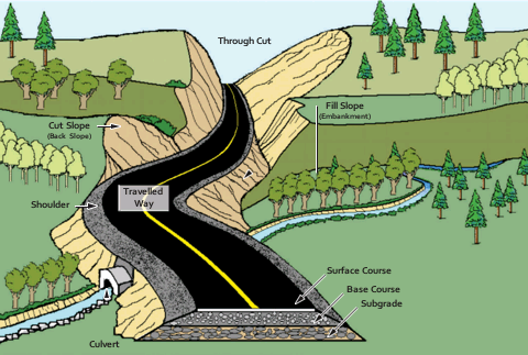
Figure 2-10 | Terms used to define roads
- Fill Slope (Embankment Slope)—The inclined slope extending from the outside edge of the road shoulder to the toe (bottom) of the fill. This is the surface formed when excavated material is placed on a prepared ground surface to construct the road subgrade and roadbed template.
- Grade (Gradient)—The slope of the road along its alignment. This slope is expressed as a percentage and is the ratio of elevation change compared to distance traveled. For example, a +4 percent grade indicates a gain of 4 units of measure in elevation for every 100 units of measure traveled.
- Natural Ground (Original Ground Level)—The natural ground surface of the terrain that existed prior to disturbance and/or road construction.
- Plan View (Map View)—View seen when looking from the sky towards the ground (bird’s-eye view).
- Reinforced Fill—A fill that has been provided with tensile reinforcement through frictional contact with the surrounding soil for the purpose of greater stability and load carrying capacity. Reinforced fills are comprised of soil or rock material placed in layers with reinforcing elements to form slopes, walls, embankments, dams, or other structures. The reinforcing elements range from simple vegetation to specialized products such as steel strips, steel grids, polymeric geogrids, and geotextiles.
- Retaining Structure—A structure designed to resist the lateral displacement of soil, water, or any other type of material. It is commonly used to support a roadway or gain road width on steep terrain. They are often constructed of gabions, reinforced concrete, timber cribs, or mechanically-stabilized earth.
- Right-of-Way—The area or footprint of land over which facilities such as roads, railroads, or power lines are built. Right-of-way is an easement that grants the right to pass over the land of another.
- Road Center Line—An imaginary line that runs longitudinally along the center of the road.
-
Roadbed—Width of the road used by vehicles, including the shoulders, measured at the top of subgrade.
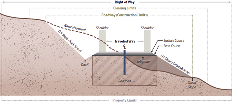
Figure 2-11 | Terms used to define roads: cross-section
- Roadway (Construction Limits or Formation Width)—Total horizontal width of land affected by the construction of the road, from the top of cut slope to the toe of fill or graded area.
- Side-Cast Fill—Excavated material pushed on a prepared or unprepared slope next to the excavation to construct the roadbed. The material is usually not compacted.
- Shoulder—The paved or unpaved area along the edge of the traveled way of the road. An inside shoulder is adjacent to the cut slope. An outside shoulder is adjacent to an embankment slope.
- Traveled Way (Carriageway)—That portion of the road constructed for use by moving vehicles including traffic lanes and turnouts (excluding shoulders).
- Through Cut—A road cut through a hill slope or, more commonly, a ridge, in which there is a cut slope on both sides of the road.
- Through Fill—Opposite of a through cut, a through fill is a segment of road that is entirely composed of fill material, with fill slopes on both sides of the road.
2.6.2 ROAD STRUCTURAL SECTION AND MATERIALS
- Borrow Pit (Borrow Site)—An area where excavation takes place to produce materials for earthwork, such as a fill material for embankments. It is typically a small area used to mine sand, gravel, rock, or soil without further processing.
- Quarry—A site where stone, riprap, aggregate, and other construction materials are extracted. The material often has to be excavated with ripping or blasting, and the material typically needs to be processed by crushing or screening to produce the desired gradation of aggregate.
2.6.3 SURFACE DRAINAGE
- Armor—Rocks or other material placed on headwalls, on soil, or in ditches to prevent water from eroding and undercutting or scouring the soil.
- Drainage Structure—A structure installed to control, divert, or move water off or across a road, including but not limited to culverts, bridges, ditch drains, fords, and rolling dips.
- French Drain (Underdrain)—A buried trench, filled with coarse aggregate, and typically placed in the ditch line along the road to drain subsurface water from a wet area and discharge it to a safe and stable location. French drains may use variable sizes of rock but do not have a drain pipe in the bottom of the trench.
- Inslope—The inside cross-slope of a road subgrade or surface, typically expressed as a percentage. Inslope is used to facilitate the draining of water from a road surface to an inside ditch. An insloped road has the highest point on the outside edge of the road and slopes downward to the ditch at the toe of the cut slope, along the inside edge of road.
- Outslope—The outside cross-slope of a road subgrade or surface, typically expressed as a percentage. Outslope is used to facilitate the draining of water from a road directly off the outside edge of the road. An outsloped road has the highest point on the uphill or inside of the road and slopes down to the outside edge of the road and the fill slope.
- Riprap—Well-graded, durable, large rock, ideally with fractured surfaces, sized to resist scour or movement by water and installed to prevent erosion of native soil material.
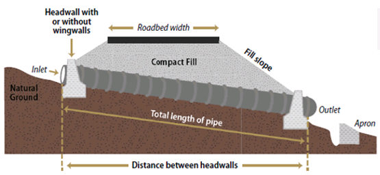
Figure 2-12 | Culvert components
2.6.4 CULVERTS AND DRAINAGE CROSSINGS
- Catch Basin—The excavated precast, or constructed basin at the inlet of a culvert cross-drain pipe for storing water and directing it into the culvert pipe.
- Culvert— A drainage pipe, usually made of metal, concrete, or plastic, set beneath the road surface to move water from the inside of the road to the outside of the road, or under the road. Culverts are used to drain ditches, springs, and streams that cross the road. The invert is the floor or the bottom of the structure at its entrance.
- Headwall—A concrete, gabion, masonry, or timber wall built around the inlet or outlet of a drainage pipe or structure to increase inlet flow capacity, reduce risk of debris damage, retain the fill material, and minimize scour around the structure.
- Inlet—The opening in a drainage structure or pipe where the water first enters the structure.
- Outlet—The opening in a drainage structure or pipe where the water leaves the structure. The outlet is usually lower than the inlet to ensure that water flows through the structure.
2.6.5 MISCELLANEOUS TERMS
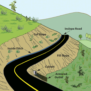
Figure 2-13 | Terms used to describe road slopes
- Angle of Repose—The maximum slope or angle at which a granular material, such as loose rock or soil, will stand and remain stable.
- Gabions—Baskets (usually made of heavy-gauge wire) filled with rocks or broken pieces of concrete (~10-20 cm in size), used for building erosion control structures, weirs, bank protection, or retaining structures.
- Road Decommissioning—Permanently closing a road through techniques that may include blocking the entrance, scattering limbs and brush on the roadbed, replanting vegetation, adding waterbars, removing fills and culverts, or reestablishing natural drainage patterns. The basic road shape, or template, is still in place. The end result is to terminate the function of the road and mitigate the adverse environmental impacts of the road.
- Road Obliteration—A form of road closure that refills cut areas, removes fills and drainage structures, restores natural contours, revegetates the area, and ultimately attempts to restore the natural ground shape and condition. Most adverse environmental impacts of the road are eliminated.
- Silt Fence—A temporary barrier used to intercept sediment-laden runoff from slopes. It is typically made of porous geotextile material.
- Streamside Management Zone—The land, together with the associated vegetation, immediately in contact with the stream and sufficiently close to have a major influence on the total ecological character and function of the stream. It is a buffer area along a stream where activities are limited or prohibited.
Back to top

